


20
W415-0299 / J / 04.14.08
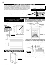
For safe and proper operation of the fi replace, follow the vent-
ing instructions exactly.
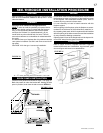
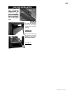
Eight (8") inches is the minimum bend radius allowed for
the 8" diameter fl exible liner.
1. Stretch the 5" diameter fl ex pipe to the required length tak-
ing into account the additional length needed for the fi nished
wall surface. Apply a heavy bead of the high temperature
sealant W573-0007 10.3oz tube (not supplied), to the inside
of the 5" liner approximately 1" from the end. Slip the liner a
minimum of 2" over the fi replace vent collar and secure with
3 #8 screws.
2. Using the 8" diameter fl ex pipe, apply high temperature
sealant or Red RTV Silicone in this location, slide a minimum
of 2" over the fi replace combustion air collar and secure with
3 #8 screws.
The air terminal may be recessed into the exterior wall or
siding by 1½", the depth of the return fl ange.
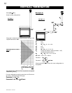
FIGURE 36
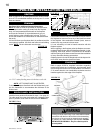
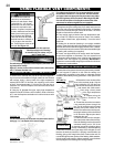
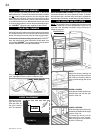
USING FLEXIBLE VENT COMPONENTS
Use only approved fl exible liner kits marked:
"Wolf Steel Approved Venting"
as identifi ed by the stamp only on
the 8” outer liner.
For optimum performance, it is recommended that horizon-
tal runs have a minimum ¼" rise per foot . All inner exhaust
and outer intake vent pipe joints may be sealed using either
Red RTV high temp silicone sealant or Black high temp Mill
Pac with the exception of the fireplace exhaust flue collar
which must be sealed using Mill Pac (not supplied).
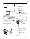
HORIZONTAL AIR TERMINAL INSTALLATION
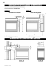
VERTICAL AIR TERMINAL INSTALLATION
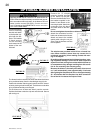
FIGURE 37
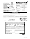
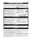
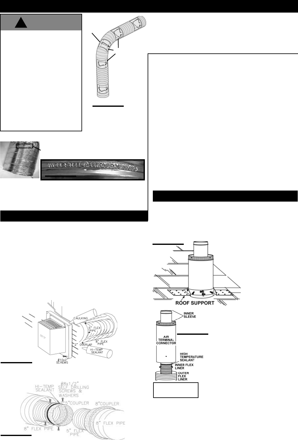
ELBOW
SPACERS
FIGURE 34
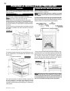
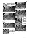
FIGURE 38
FIGURE 39
3. Insert the vent pipe through the fi restop. Position and secure
the fi replace using the nailing tabs (2 per side) and/or secure
to the fl oor using screws inserted through the two ¼" diameter
holes in the front left and right corners of the base. The liners
should be fl ush with the exterior wall.
4. From outside, apply a bead of the high temperature seal-
ant or Red RTV Silicone may also be used in this location,
to the inside of both liners, approximately 1" from the end of
each liner.
5. Holding the air terminal (lettering in an upright, readable
position), insert into both liners with a twisting motion to ensure
that both the terminal sleeves engage into the liners / sealant.
Secure the terminal to the exterior wall and make weather tight
by sealing with caulking (not supplied).
6. If more vent pipe needs to be used to reach the fi replace,
couple them together as illustrated. The vent system must
be supported approximately every 3 feet for both vertical and
horizontal runs. Use support ring assembly W010-0380 or
equivalent noncombustible strapping to maintain the minimum
1" clearance to combustibles.
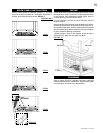
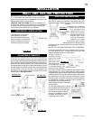
1. Fasten the roof support to the roof using the screws provided.
The roof support is optional. In this case the venting is to
be adequately supported using either an alternate method
suitable to the authority having jurisdiction or the optional roof
support.
2. Stretch the inner aluminum fl ex
liner to the required length. Slip the
liner a minimum of 2” over the inner
sleeve of the air terminal connector
and secure with 3 #8 screws.
Seal using a heavy bead
of the high temperature
sealant.
3. Repeat using the
outer aluminum flex
liner.
4. Thread the air terminal connector
/ liner assembly down through the
roof. The air terminal must be located
vertically and plumb. Attach the air
terminal connector to the roof support,
ensuring that the top of the air terminal
is 16” above the highest point that it
penetrates the roof.
5. Remove nails from the shingles,
above and to the sides of the chimney.
Place the fl ashing over the air terminal
connector leaving a min. 3/4” of the
air terminal connector showing above
the top of the fl ashing. Slide the fl ashing
underneath the sides and upper edge of the shingles. Ensure
that the air terminal connector is properly centred within the
fl ashing, giving a 3/4” margin all around. Fasten to the roof. Do
not nail through the lower portion of the fl ashing. Make weather-
tight by sealing with caulking. Where possible, cover the sides
and top edges of the fl ashing with roofi ng material.
FIGURE 35
!
WARNING
Do not allow the inside liner
to bunch up on horizontal or
vertical runs and elbows. Keep
it pulled tight. A 1 1/4" air gap
between the liner and outer liner
all around is required for safe
operation. A spacer is required at
the start, middle and end of each
elbow to ensure this gap is main-
tained. Spacers are attached
to the inner fl ex liner at prede-
termined intervals to maintain a
1 1/4" air gap to the outer fl ex
liner. These spacers must not be
removed. See Figure 34.
DO NOT CLAMP THE
FLEXIBLE LINER