


7
W415-0314 / C / 01.15.04
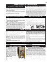
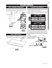
For ease of accessibility, an optional remote wall switch
or millivolt thermostat may be installed in a convenient
location. Route 2-strand solid core millivolt wire from
the gas fireplace insert to the wall switch / millivolt ther-
mostat. The recommended maximum lead length de-
pends on the wire size:
WIRE SIZE MAX. LENGTH
14gauge 100 feet
16gauge 60 feet
18gauge 40 feet
Do not connect either the wall switch, thermo-
stat or gas valve to electricity (110 VOLTS).
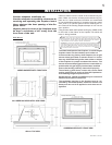
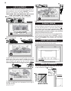
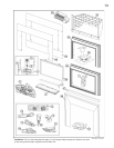
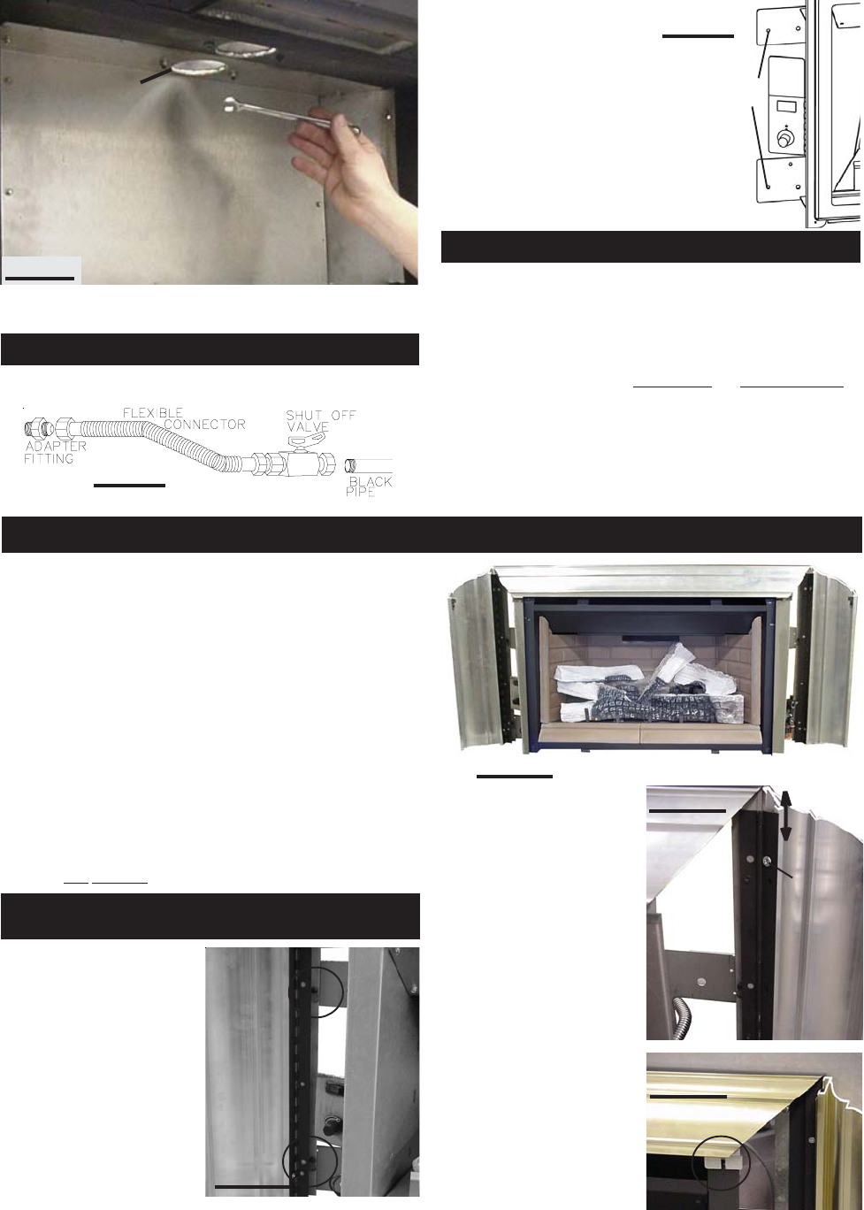
To adjust the trim: If the mi-
tre is out of alignment, open
each side and loosen the
two screws at either side
trim hinge. Slide the trim up
or down to adjust and re-
tighten screws. There is
also a very slight in/out ad-
justment that can be made.
Note: Since the side pan-
els open and close, to ac-
cess the controls, a gap is
necessary at the mitre
joint.
The top trim piece has an
adjustable securing bracket
which enables the trim to be
secured to the firebox shell.
In order to close off the fireplace opening or if the opening
is larger than the 3- or 4-sided aluminium extrusion trim
kits, it is recommended to reduce the opening using a
noncombustible material such as ceramic tile, marble, etc
or the GDIBP3 or GDIBP4 backer plate kits. The GDIBP3
backer plate is able to fit an opening of 52" x 33½". The
GDIBP4 backer plate is able to fit an opening of 52" x 42¾".
The outside edge of the backer plate is finished off with
gold trim included in each kit. A GDIBP3D 3 sided deluxe
backer plate complete with marquis trim may also be used
to complete the installation. This kit is able to fit an open-
ing of 57" x 33½". Detailed installation instructions are in-
cluded with each kit.
If this unit is being installed into an existing wood burning,
zero clearance fireplace, then be aware of this precaution:
Any circulation air opening may be covered (with mate-
rial) but not sealed!
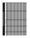
The insert can be equipped
with either a 3- or 4-sided
trim kit to finish off the fire-
place opening. Slide the
trim assembly over the key-
holes (2 per side) and drop
into place. If installing the
optional 3- or 4-sided
backer plate (GDIBP3 or
GDIBP4), it must be hung
prior to the trim kit installa-
tion using the same key-
holes.
FIGURE 10
FIGURE 12
LOOSEN
SCREWS
SLIDE TO
ADJUST
FIGURE 13
FIGURE 11
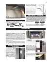
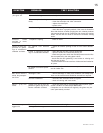
VENT
CONNECTION
ASSEMBLY
FIGURE 7
FINISHING
ALUMINIUM EXTRUSION TRIM KIT
INSTALLATION
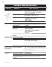
6. Reinstall the back wall, followed by the log support, us-
ing the perimeter screws removed in step 4.
Install suitable supply piping connection to the
3
/
8
" flex con-
nector supplied (as per local gas codes).
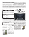
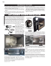
GAS INSTALLATION
The insert may now be
pushed into its final position
inside the wood-burning fire-
place. Secure the insert to the
fireplace using perforated
strapping attached to the two
securing holes on either side
of the unit as shown. We rec-
ommend that the trim be in-
stalled before the unit is
placed into its final position.
SECURING
HOLES
WALL SWITCH / THERMOSTAT
FIGURE 8
FIGURE 9