


6
W415-0314 / C / 01.15.04
2. Gently stretch the liners to the required lengths and in-
sert into the chimney. Place the terminal onto the top of the
chimney cap and fit the flashing plate to suit. Make weather
tight by sealing with caulking (not supplied) and fasten to
the chimney with screws and plugs (not supplied).
3. NOTE: If there is not enough ceiling height between the
fireplace and the insert to allow the flexliner connection on
the top of the unit to be made, proceed to step 4.
If there is enough ceiling height, connect the 3" stainless
steel flexliner to the exhaust collar closest to the top front
on the unit. See figure 1c. Connect the intake flexliner to the
remaining rear collar. Secure and seal.
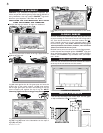
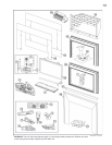
4. Both the log support and the back wall must be removed
in order to gain access to the vent connection assembly.
Both the back wall and log support are detached by remov-
ing the 12 perimeter screws of the back wall and the 3
screws located at the back of the log support. Remove the
vent connection assembly.
NOTE: The vent connection assembly collars are not spe-
cific until the stainless steel flexliner has been attached to
one side. This now designates the side as exhaust. The
exhaust collar must be positioned closest to the front open-
ing of the insert. SEE FIGURE 1c. Secure and seal the
flexliners.
5. To reinstall the vent connection
assembly, reach in through the in-
sert and manoeuvre the vent con-
nection assembly through the
opening in the firebox top. Take care
not to damage the gasket. Secure
the assembly using the four studs
and ¼-20 hex nuts.
BACK WALL
LOG SUPPORT
FIGURE 5
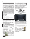
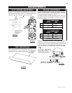
Move the insert close to its final position inside the wood-
burning fireplace. This unit is equipped with 6 levelling
screws located as follows: two are on either side of the
circulation blower on the rear panel; four are located front
and back on either side beneath the log support. Level
using four of the levelling screws. See Figure 1a. Levelling
the unit will eliminate rocking or excessive noise when the
fan is in operation. Once the unit is level, move it partially
into place within the fireplace to allow for all connections to
be made. It is not practical to level the insert once it has
been installed. Determine the required depth prior to in-
stalling the unit and adjust the four levelling screws accord-
ingly.
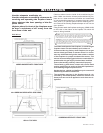
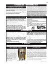
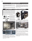
Chimney installation must conform to both national and
local code requirements. The chimney must be lined with
one 2" or 3" diameter liner for intake and one 3" diameter
liner for exhaust. The minimum and maximum vent lengths
are 10 and 35 feet respectively. Recommended Napoleon
kits come in 3 lengths:
While the liners must be continuous from the fireplace to the
chimney cap, to achieve the needed length, they may be
coupled, using an aluminium coupler, provided installation
is sealed & secured.
We recommend that exhaust vents that pass through
unheated spaces, such as a garage or attic, be
wrapped in a protective sleeve to minimize condensa-
tion and reverse flow symptoms.
This unit is approved for use with a 2" liner for air intake
and a 3" liner for exhaust. For best performance,
however, it is recommended to use two 3" liners.
If a 2" liner is used for the intake, it is necessary to
adjust the primary air shutter. See "Air Shutter Settings".
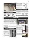
1. OUTSIDE: Slip the
one end of a liner a
minimum of 2" over the
collar of the air terminal.
Secure using 3 screws.
Then seal the joint and
screw heads with high
temperature sealant.
Repeat with the other liner
to the exhaust collar of the
terminal.
NOTE: Connect the supplied 3'
of stainless steel flexliner to the
exhaust liner (already attached to
the terminal) using the coupler
(also supplied). Secure and seal
before dropping down the chim-
ney.
FIGURE 4
VENT CONNECTION
ASSEMBLY
FIGURE 6
INSERT VENT CONNECTION
CHIMNEY CONNECTION
1-2" & 1-3" DOUBLE PLY ALUMINUM LINER-INLET AND EXHAUST &
2-3" TO 2" REDUCER:
GDI-2320KT VENT KIT 20FT
GDI-2325KT VENT KIT 25FT
GDI-2335KT VENT KIT 35FT
2-3" DOUBLE PLY ALUMINUM LINER-INLET AND EXHAUST:
GDI-320KT VENT KIT 20FT
GDI-325KT VENT KIT 25 FT
GDI-335KT VENT KIT 35 FT
FIGURE 2
ALUMINUM
FLEXLINER
COUPLER
STAINLESS
STEEL
FLEXLINER
FIGURE 3