


45
GAS-FIRED HEATER Installation Manual
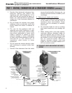
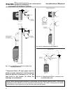
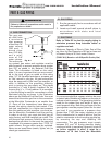
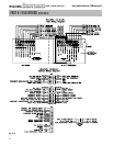
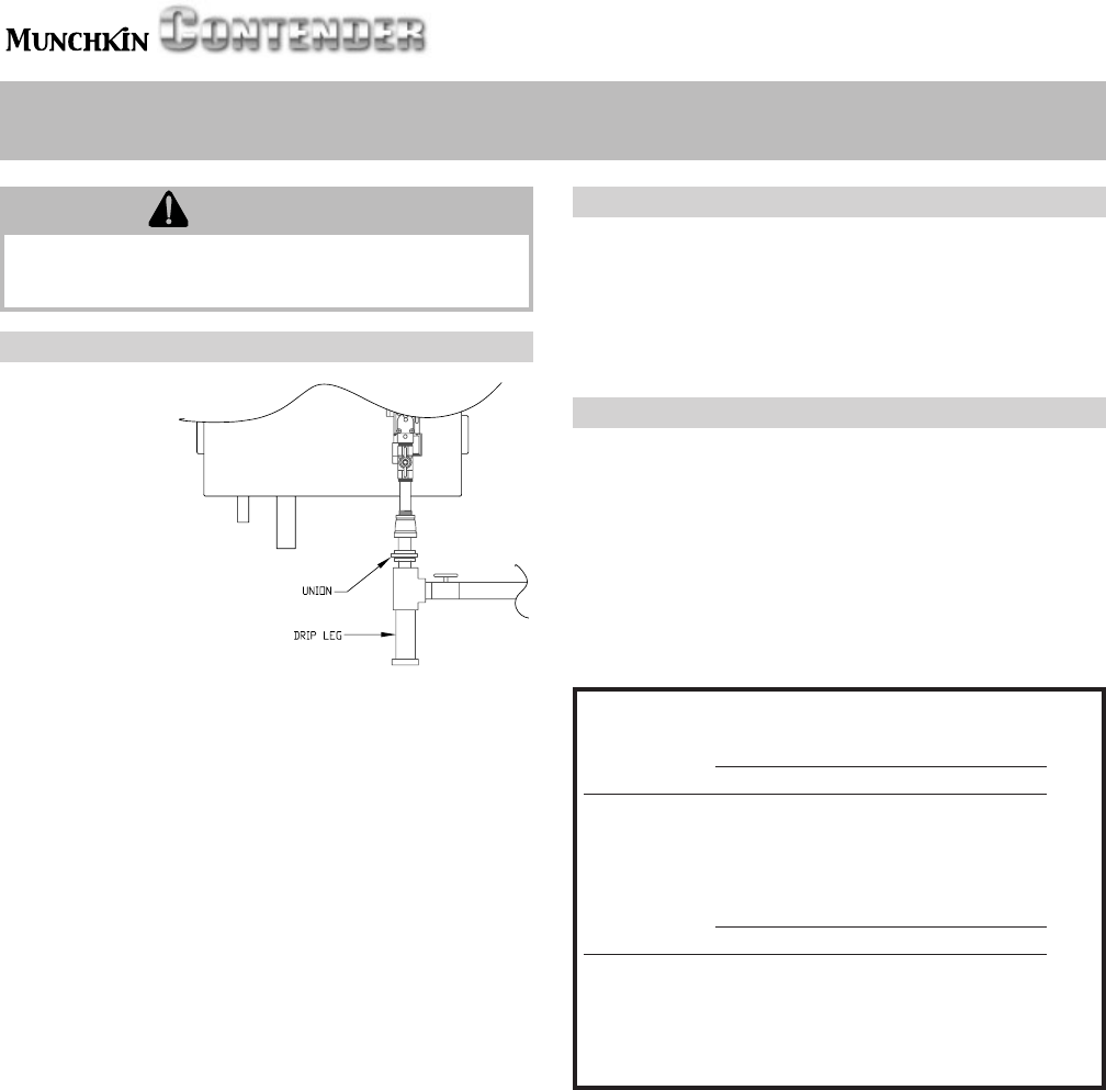
A. GAS CONNECTION
The gas sup-
ply shall have
a maximum
inlet pressure
of less than 14"
water column
(350 mm), ½
pound pres-
sure (3.5 kPa),
and a mini-
mum of 3.5"
water column.
The entire pip-
ing system, gas meter and regulator must be
sized properly to prevent pressure drop greater
than 0.5" as stated in the National Fuel Gas
Code. This information is listed on the rating
plate. It is very important that you are connect-
ed to the type of gas as noted on the rating
plate. "LP" for liquefied petroleum, propane gas
or, "Nat" natural or city gas. All gas connections
must be approved by the local gas supplier, or
utility in addition to the governing authority,
prior to turning the gas supply on. The nipple
provided is ½" with a factory installed. Do not
remove this ¾" x ½" bell reducer! It is mandato-
ry that this fitting is used for connection to a field
fabricated drip leg as shown in the illustration
above per the National Fuel Gas Code. You must
ensure that the entire gas line to the connection
at the Munchkin Contender is no smaller than
¾". Once all the inspections have been per-
formed, the piping must be leak tested. If the
leak test requirement is a higher test pressure
than the maximum inlet pressure, you must iso-
late the Munchkin Contender from the gas line.
In order to do this, you must shut the gas off
using factory and field-installed gas cocks. This
will prevent high pressure. Failure to do so may
damage the gas valve. In the event the gas valve
is exposed to a pressure greater than ½ PSI, 14"
water column, the gas valve must be replaced.
Never use an open flame (match, lighter, etc.) to
check gas connections.
PART 8: GAS PIPING
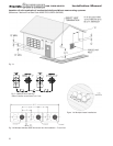
B. GAS PIPING
1. Run the gas supply line in accordance with all
applicable codes.
2. Locate and install manual shutoff valves in
accordance with state and local
requirements.
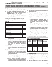
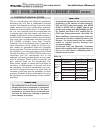
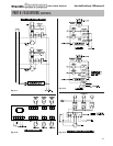
C. GAS TABLE
Refer to Table 8.2 to size the supply piping to
minimize pressure drop between meter or
regulator and unit.
Maximum Capacity of Pipe in Cubic Feet of Gas
per Hour for Gas Pressures of 0.5 psi or Less and
a Pressure Drop of 0.3 Inch water Column
(TABLE 8-2) (Based on a 0.60 Specific Gravity Gas)
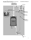
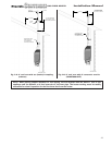
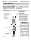
It is recommended that a soapy solution be used
to detect leaks. Bubbles will appear on the pipe to
indicate a leak is present. The gas piping must be
sized for the proper flow and length of pipe, to
avoid pressure drop. Both the gas meter and the
gas regulator must be properly sized for the total
gas load. If you experience a pressure drop
greater than 1" WC, the meter, regulator or gas
line is undersized or in need of service. You can
attach a manometer to the incoming gas drip leg,
by removing the cap and installing the
manometer. The gas pressure must remain
between 3.5" and 14" during stand-by (static)
mode and while in operating (dynamic) mode. If
an in-line regulator is used, it must be a
minimum of 10 feet from the Munchkin
WARNING
Failure to follow all precautions could result in
fire, explosion or death!
NNoommiinnaall
IIrroonn PPiippee IInntteerrnnaall LLeennggtthh ooff PPiippee ((FFeeeett))
SSiizzee DDiiaammeetteerr
((iinncchheess)) ((iinncchheess)) 1100 2200 3300 4400 5500 6600 7700
33//44 ..882244
278 190 152 130 115 105 96
BBTTUU''SS
11 11..004499
520 350 285 245 215 195 180
PPEERR
11 11//44 11..338800
1,050 730 590 500 440 400 370
HHOOUURR
11 11//22 11..661100
1,600 1,100 890 760 670 610 560
}
xx11,,000000
8800 9900 110000 112255 115500 117755 220000
33//44 ..882244
90 84 79 72 64 59 55
BBTTUU''SS
11 11..004499
170 160 150 130 120 110 100
PPEERR
11 11//44 11..338800
350 320 305 275 250 225 210
HHOOUURR
11 11//22 11..661100
530 490 460 410 380 350 320
}
xx11,,000000
Fig. 8-1