


37
GAS-FIRED HEATER Installation Manual
PART 7: VENTING, COMBUSTION AIR & CONDENSATE REMOVAL
(CONTINUED)
f. Provide 4 feet horizontal clearance from
electrical meters, gas meters, gas
regulators and relief equipment. In no
case shall the exit terminal be above or
below the aforementioned equipment
unless the 4 foot horizontal distance is
maintained.
g. Do not locate the exhaust over public
walkways where condensate could drip
and/or freeze and create a nuisance or
hazard.
h. The vent for this appliance shall not
terminate over public walkways; or near
soffit vents or crawl space vents or other
area where condensate or vapor could
create a nuisance or hazard or cause
property damage; or where condensate
or vapor could cause damage or could be
detrimental to the operation of
regulators, relief valves, or other
equipment.
i. Do not locate the exhaust directly under
roof overhangs to prevent icicles from
forming.
j. Provide 4 feet clearance from the inside
corner of vertical walls, chimneys, etc., as
well as horizontal corners created by roof
overhangs.
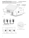
2. Determine air intake vent location.
a. Provide 1 foot clearance from the bottom
of the intake air vent and the level of
maximum snow accumulation. Snow
removal may be necessary to maintain
clearances.
b. Do not locate intake air vent in a parking
area where machinery may damage the
pipe.
c. When venting with a two pipe system,
maximum distance between intake air
vent and exhaust vent is 6 feet (1.8 m).
Minimum distance between exhaust vent
and intake air vent on single heater is 8”
(0.2 m) center-to-center. Minimum
distance between exhaust vents and
intake air vents on multiple heaters is 8”
(0.2 m) center-to-center.
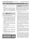
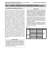
E. EXHAUST VENT AND INTAKE AIR VENT
SIZING
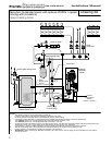
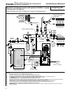
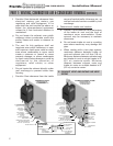
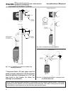
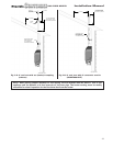
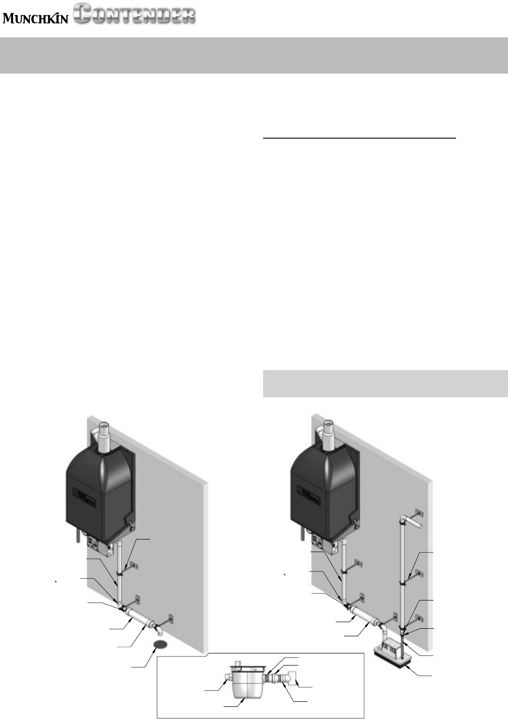
CONDENSATE REMOVAL TO
SUGGESTED SETUP FOR
CONDENSATE PIPING
CONDENSATE
CUP ASSEMBLY
DETAILS
FLOOR DRAIN
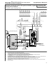
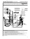
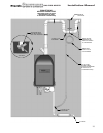
CONDENSATE PIPING W/PUMP
SUGGESTED SETUP FOR
CONDENSATE REMOVAL
TO OUTSIDE SOURCE
(2 SHOWN)
3/4" PIPE
HANGER
HOSE BARB
PVC ADAPTER
NEUTRALIZER
3/4" PVC PIPE
3/4" SOCKET X
(2 SHOWN)
1/2" THREAD
N1100 CONDENSATE
3/8" ID TUBING
BY DISTANCE TO FLOOR)
(LENGTH DETERMINED
BE INSTALLED WITH A
ELBOW
ASSEMBLIES
90
PVC ADAPTER
3/4" NPT
3/8" TUBE X
1/2" NPT THREAD
PITCH OF 1/4" PER FOOT
3/4" PVC
3/4" SOCKET X
HORIZONTAL LINES MUST
CONDENSATE
PUMP
PVC UNION
SOCKET PVC
PVC TEE
CUP ASSEMBLY
ADAPTER
3/4" SOCKET
3/4" NPT PVC NIPPLE
CONDENSATE
3/4" NPT FEMALE
3/4" THREAD X
CONDENSATE
SWITCH
BE INSTALLED WITH A
90
FLOOR DRAIN
N1100 CONDENSATE
HORIZONATAL LINES MUST
NEUTRALIZER
ELBOW
PITCH OF 1/4" PER FOOT
DISTANCE TO FLOOR)
3/4" PVC PIPE
(LENGTH DETERMINED BY
1/2" THREAD
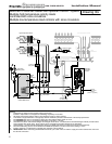
(2 SHOWN)
(2 SHOWN)
PVC ADAPTER
3/4" PVC
3/4" SOCKET X
3/4" PIPE
HANGER
ASSEMBLIES