JIMMY SERIES HYDRAULIC REBAR BENDERS — OPERATION AND PARTS MANUAL — REV. #9 (01/04/08) — PAGE 18
Positioning the Rebar Bender (Method 3)
For Model JB5135
1. Place the pump control valve lever
(Figure 8) in the
neutral
position.
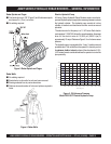
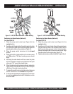
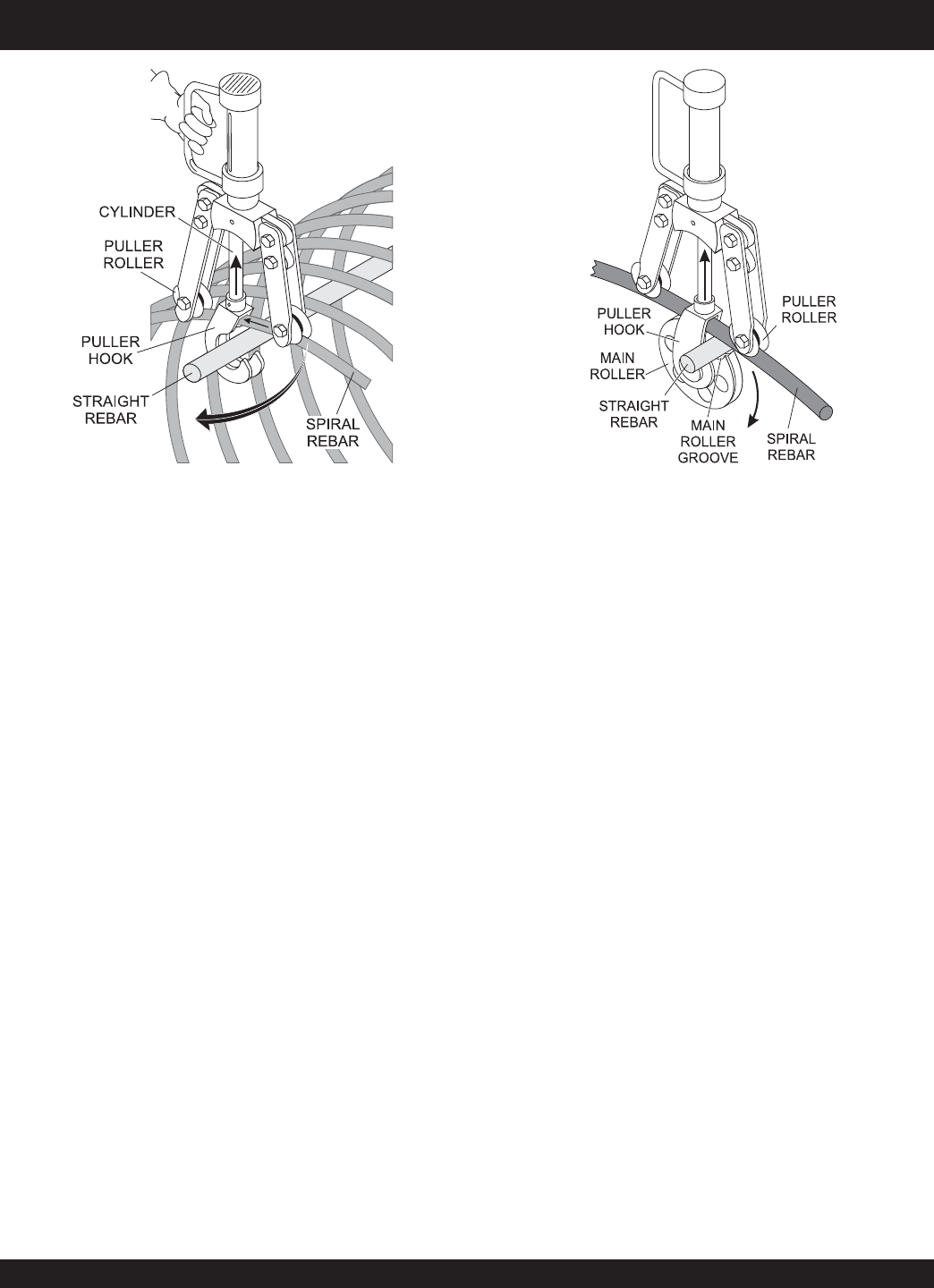
2. Send the end of the spiral rebar through the gap in the puller
hook. Secure the puller hook around the straight rebar and
align the puller rollers on the spiral rebar (Figure 15).
3. Place the pump control valve lever in the
forward
position.
4. Place and hold the toggle switch on the remote control
unit (ON position). The rebar bending process should
begin.
5. Activating the rebar bender will then cause the puller
hook and cylinder to retract and curl the end of the spiral
rebar up to 135° around the straight rebar.
6. When the desired angle has been achieved, release the
toggle switch on the remote control unit. This will stop the
retraction of the puller hook and cylinder.
7. To extend the puller hook and cylinder, place the pump
control valve lever in the
reverse
/retract position.
8. To remove the rebar bender, place the pump control
valve
lever in the
neutral
position
and lift the bender over the
end of the rebar.
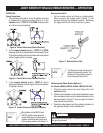
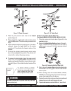
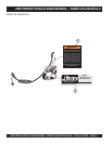
Figure 15. JB5135 Rebar Placement — Rebar Bending
JIMMY SERIES HYDRAULIC REBAR BENDERS — OPERATION
Positioning the Rebar Bender (Method 4)
For Model JB7135
1. Place the pump control valve lever
(Figure 8) in the
neutral
position.
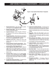
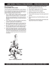
2. Send the end of the spiral rebar through the gap between
the puller hook and main roller. Rotate the main roller so
that the main roller groove is in the 1 o’clock position.
Secure the straight rebar in the main roller groove. Align
the puller rollers on the spiral rebar (Figure 16).
3. Operate rebar bender as outlined in Method 3, steps 3 thru 8.
Figure 16. JB7135 Rebar Placement — Rebar Bending


