


JIMMY SERIES HYDRAULIC REBAR BENDERS — OPERATION AND PARTS MANUAL — REV. #9 (01/04/08) — PAGE 13
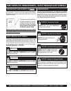
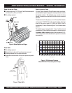
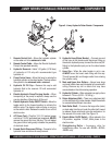
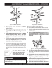
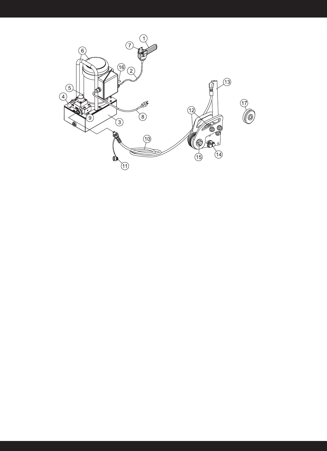
1. Remote Control Unit – Allows the hydraulic cylinder
on the rebar unit to be
advanced
or
held
.
2. Remote Control Cable – Allows the Electric-Hydraulic
Pump to be operated remotely.
3. Hydraulic Reservoir– Holds 1.00 gallon (3.78 liters)
of hydraulic oil. Fill only with recommended type
hydraulic oil.
4. Pump Control Lever – Move this lever to actuate the
hydraulic cylinder on the rebar bender. The lever allows
the cylinder to be
advanced
,
held
or
returned.
5. Hydraulic Oil Fill Cap – Remove this cap to add
hydraulic fluid to the reservoir. Fill with commercial
hydraulic oil.
6. Electric-Hydraulic Pump/Carrying Handle – When
transporting of the pump is required, always use the
carrying handle or lifting bale to lift the unit.
7. Electric-Hydraulic Pump ON/OFF Switch – Move the
toggle switch to the forward position to activate the
electric motor. The electric motor will stay on as long
as the switch is held. Release the switch to turn off the
electric motor.
8. AC Power Cord – Plug this 10 ft. (3.0 meters) power
cord into a 115 VAC grounded type receptacle. NEVER
remove the ground pin from the plug. This will defeat
the ground circuit and greatly increase the possibility
of electrical shock.
9. Female Quick Disconnect Fitting – Connects to the
hydraulic hose and allows for easy removal.
10. Hydraulic Hose (Rebar Bender) – Connect one end
of this hose to the female quick disconnect fitting on
the electric-hydraulic pump, connect the other end (90°
fitting) to the hydraulic input port on the rebar bender
cylinder.
11. Hose Cap – When the rebar bender is not in use,
ALWAYS cover the hose’s male fitting with this cap.
This will prevent dirt and foreign matter from entering
the cylinder cavity.
12. Main and Upper Arm Rollers – Always keep large
and small rollers clean and lubricated to insure smooth
rolling. Remove any dirt or debris that may have
accumulated on the rollers during operation.
13. Hydraulic Cylinder – When actuated can apply a force
between 2~10 tons (2,032 ~10,160 kg.)
14. Rebar Adjustment Bolt – There is an adjustment bolt
on the side plate of the rebar bender. Adjust these bolts
to accommodate different size rebar.
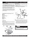
15. Main Roller Shaft – To remove the large roller (main)
or stuck rebar from the unit, push the roller shaft inward
to release. Some units have a pin-clip mechanism for
the removal of the main roller. See Figure 14.
16. Electric Motor On/Off Switch – When placed in the
ON position, supplies 115VAC, 60Hz power to the
electric motor.
17. Straightening Roller – Accessory roller for
straightening rebar. For use with JB5090, JB7090,
JB8090 only.
Figure 6. Jimmy Hydraulic Rebar Bender Components
JIMMY SERIES HYDRAULIC REBAR BENDERS — COMPONENTS