


JIMMY SERIES HYDRAULIC REBAR BENDERS — OPERATION AND PARTS MANUAL — REV. #9 (01/04/08) — PAGE 16
OPERATION
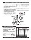
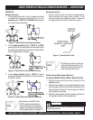
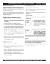
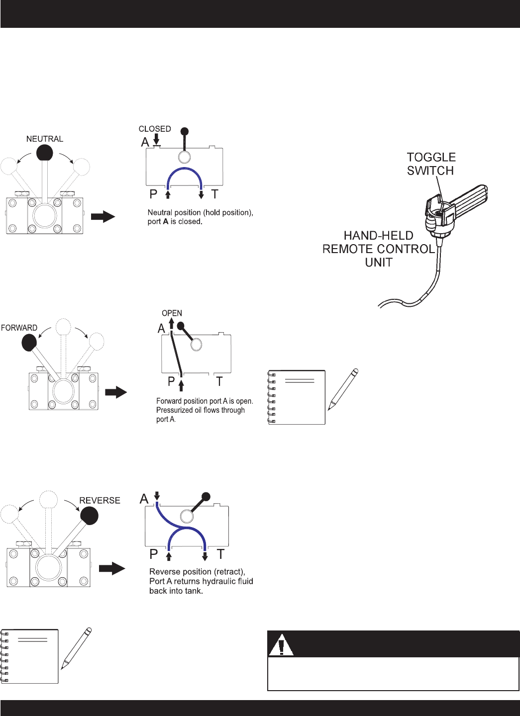
Control Valve Lever
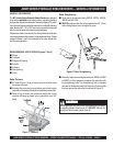
1. This hydraulic pump has a 3-way, 3-position valve that
is activated by a control valve lever (Figure 8). In the
neutral
position, “PORT A” is CLOSED, meaning there
is no flow of pressurized fluid.
2. In the
forward (extend)
position, “PORT A” is OPEN,
meaning the flow of pressurized fluid is allowed (Figure
9) and the hydraulic cylinder will extend once the remote
control toggle switch is pressed.
JIMMY SERIES HYDRAULIC REBAR BENDERS — OPERATION
Figure 8. Control Valve Lever (Neutral Position)
Figure 9. Control Valve Lever (Forward Position)
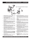
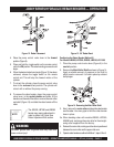
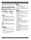
Remote Control Unit
1. On the remote control unit there is a toggle switch.
When pressed, this toggle switch (Figure 11) will
activate (extend) the hydraulic cylinder. Releasing
the toggle switch will hold the cylinder in place.
Figure 11. Remote Control Unit
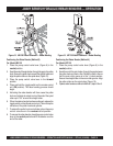
Positioning the Rebar Bender (Method 1)
For Models JB5090, JB7090, JB8090, JB9180, JB11090
1. Place the pump control valve lever
(Figure 8) in the
neutral
position.
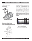
2. Place the rebar bender over the rebar between the main
roller and upper roller arm at the desired elevation of the
bend as shown in Figure 12. Use vise-grips to hold the
rebar bender base in place.
3. Rotate the rebar bender until the hydraulic cylinder is in
the opposite direction of the desired bend.
3. In the
reverse
(retract)
position, “PORT A” returns
hydraulic fluid back into tank (Figure 10) and the hydrau-
lic cylinder retracts.
Figure 10. Control Valve Lever (Reverse Position)
NOTE
The Remote Control Unit does not
retract the hydraulic cylinder. The
retraction of the cylinder must be
done manually (Power Unit).
Make certain the area is clear of bystanders before starting
the bending process.
CAUTION
CAUTIONCAUTION
CAUTIONCAUTION
CAUTION
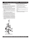
NOTE
The cylinder on the JB5135 and
JB7135 models retract when the
control valve lever is in the forward
position and extend when the lever is
in the reverse position. See Figure 15.