


78D0011
19
WDV Series Gas Fireplace
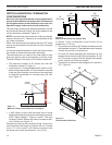
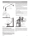
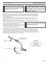
1. Flexible UL1777 listed venting may be used in any venting application where rigid direct vent components
can be used.
Flex kits may not be modified. Flex kits may be
added to the end of a vent run made of rigid vent sections using pipe
manufacturer's approved flex to pipe adapters. This may occur
only if doing so does not violate any of the venting length, height,
routing, horizontal to vertical ratio requirements or clearance
considerations detailed in this manual.
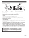
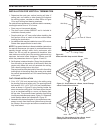
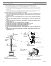
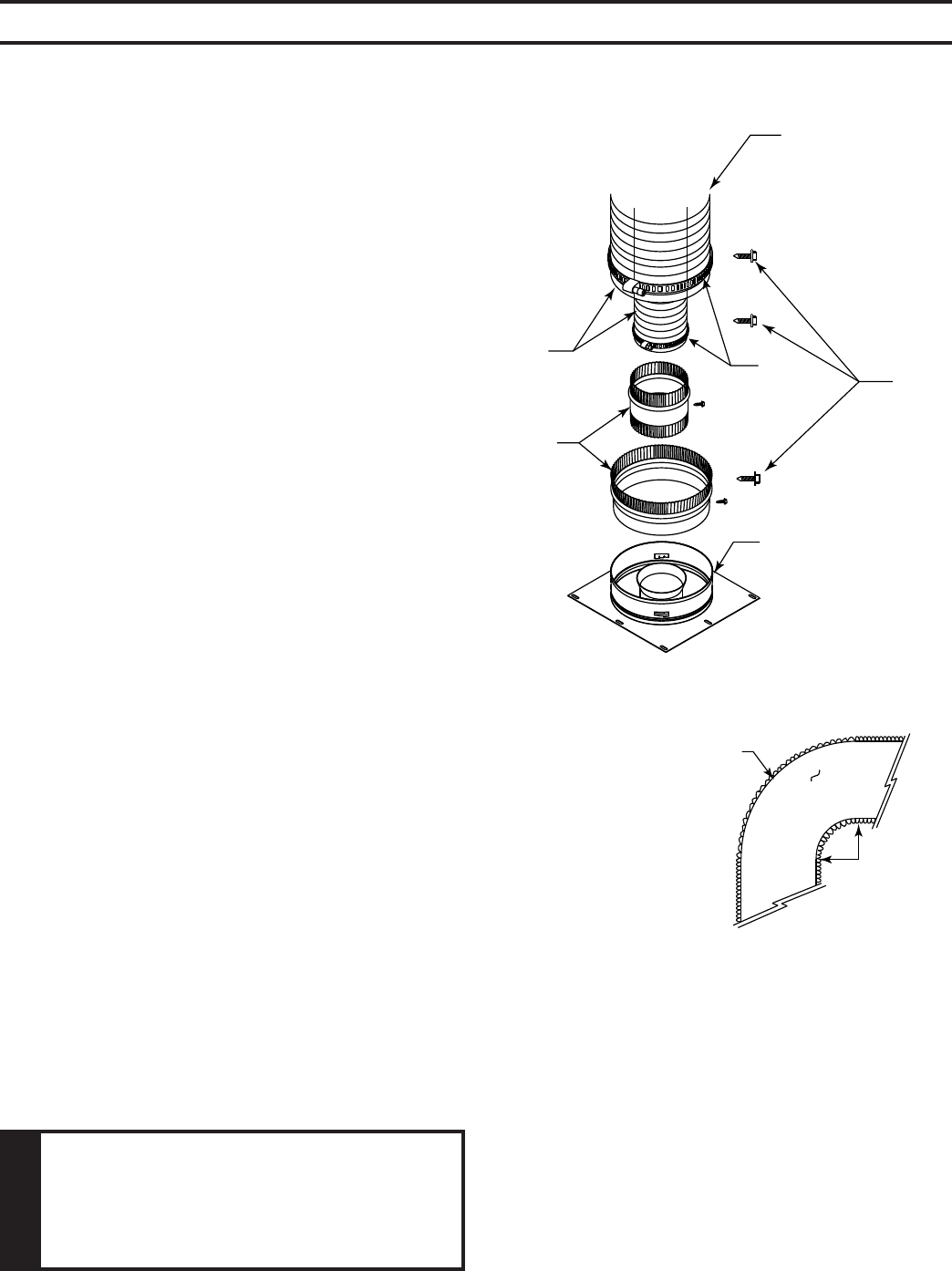
2. The flex adapter starter kit (DVF8A/8) is used to attach flex
venting to the appliance starting collar. It includes 5" inner
and 8" outer adapter rings. Figure 24
• The inner and outer adapter rings are required to start
all flex runs.
• Never install damaged or torn flexible venting.
• Over tightening clamps may rip, tear, or otherwise
damage flexible venting.
• The adapter kit does not include individual pipe sec-
tions which may be purchased separately. (UL1777
listed type venting only.)
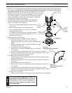
3. Start the flexible vent as follows:
A. Installing the inner flex adapter and pipe. Figure 24
1. Insert the long side of the 5" inner ring into
exhaust pipe, gently tap to seat into place, and secure with
screws.
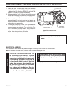
2. Slide the small gear clamp over the inner flexible vent pipe,
and push out of the way.
3. Pull and extend the inner flexible vent.
4. Slide the inner vent onto the adapter collar, for a minimum
1C\v" overlap.
5. Locate the clamp at approximately 3/4" from the flex end and tighten.
6. Secure the clamped inner section with three self-tapping screws, drilled
equidistant, just above the clamp perimeter.
B. Installing the outer flex pipe. Figure 24
1. Firmly insert the 8" outer adapter ring into the outer appliance starting collar
and secure with screws.
2. Slide the large gear clamp over the outer flexible vent pipe, and push out
of the way.
3. Pull and extend the outer flexible vent.
4. Slide the outer vent onto the appliance collar outer adapter for a minimum
1C\v" overlap.
5. Locate the clamp at approximately 3/4" from the flex end and tighten.
6. Secure the clamped outer section with three self-tapping screws, drilled
equidistant, just above the clamp perimeter.
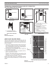
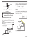
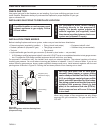
C. Routing UL1777 flex pipe.
1. Always maintain the required clearance when routing the flex vent assembly.
FP1972
appliance connection
UL1777
Flex Vent
Screws
(3 places,
equidistant just
above gear
clamp)
1C\v" Flex-
ible Pipe
and Adapter
Outer
DVF8A
Inner Adapter
Outer Adapter
Appliance
Starting Collar
Figure 24 -
Typical Appliance Connection
FP1973
flex pipe bend
UL1777
Flex Vent
5° Radius
Figure 25 -
Minimum Radius for Flex
Vent Section
FP1973