


14
78D0011
WDV Series Gas Fireplace
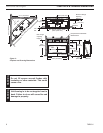
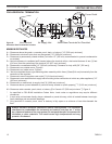
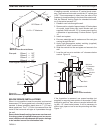
The Vent Graph, showing the relationship between vertical
and horizontal side wall venting, will help to determine the
various dimensions allowable. Figure 10
Horizontal and vertical sections of this vent system
require a minimum of 1" clearance to combustibles at the
top, sides and bottom.
When vent exits through foundations less than 20" below
outcrop, the termination must be flush up with outcropped
wall above.
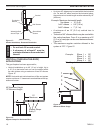
It is best to locate the fireplace in such a way that minimizes
the number of offsets and horizontal vent length.
The horizontal vent run refers to the total length of vent
pipe from the flue collar of the fireplace (or the top of the
Transition Elbow) to the face of the finished outside wall.
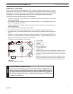
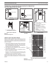
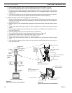
• The maximum number of 90° elbows per side wall
installation is three (3). Figure 11
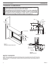
• A minimum of 12" is required before a 90° elbow. If a 90°
elbow is fitted directly after 12" vertical section mounted
to the top of the fireplace, the maximum horizontal vent
run before the termination or a vertical rise is 36” (914
mm). Figure 12
FP1176
max 90 bends
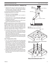
Figure 11 -
Maximum Three (3) 90° Elbows Per Installation
3 x 90°
Elbows
12" Min.
FP1176
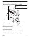
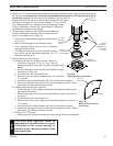
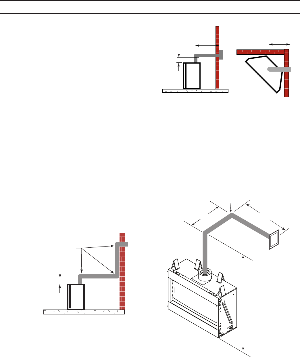
In Figures 13 and 14 dimension A plus B must not be
greater than 17' (5.2 m).
• The maximum number of 45° elbows permitted per side
wall installation is two (2). These elbows can be installed
in either the vertical or horizontal run.
• For each 45° elbow installed in the horizontal run, the
length of the horizontal run MUST be reduced by 18" (45
cm). This does not apply if the 45° elbows are installed
on the vertical part of the vent system.
• The maximum number of elbow degrees in a system is
270°. Figure 15
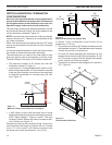
Figure 12 -
Maximum Horizontal Run with No Rise
Max 20"
Max 20"
36"
(914 mm)
Max.
36"
(914 mm)
Max.
FP1177
max horizontal run
12”
(610 mm)
FP1177
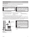
• If a 90° elbow is used in the horizontal vent run (level
height maintained) the horizontal vent length is reduced
by 36". Refer to Page 17, Figures 11 and 12. This does
not apply if the 90° elbows are used to increase or redi-
rect a vertical rise. Figure 14
Example: According to the vent graph (Page 13) the maxi-
mum horizontal vent length in a system with a 10' vertical
rise is 17Z\x’ (5.3 m) and if a 90° elbow is required in the
horizontal vent it must be reduced to 14Z\x' (4.4 m).
Figure 13 -
Horizontal Run Reduction
A
B
10’
90°
FP2427
Horizontal run
reduction
FP2427