


54D0700 25
H
X
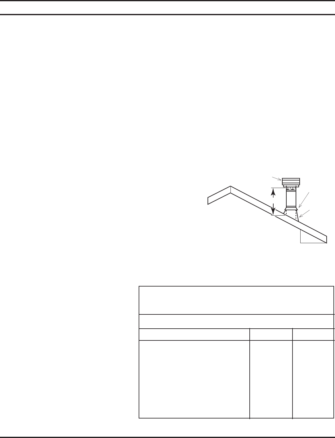
12"
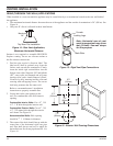
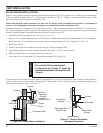
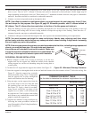
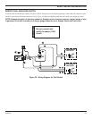
TERMINATION HEIGHT TABLE
Use this table to determine the minimum height above the roof.
Minimum Height
Roof Pitch Feet Meters
Flat to 7/12 1 0.3
Over 7/12 to 8/12 1.5 0.46
Over 8/12 to 9/12 2 0.61
Over 9/12 to 10/12 2.5 0.76
Over 10/12 to 11/12 3.25 0.99
Over 11/12 to 12/12 4 1.22
Over 12/12 to 14/12 5 1.52
Termination
Cone fl ashing
Storm collar
Figure 35 - Minimum Chimney Clearance
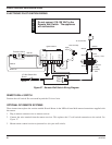
VENT INSTALLATION
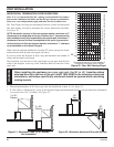
3. Cut a hole in the roof using the locating hole as a center point. (Cover any exposed open vent pipes before cutting
hole in roof). The 9
1
/2"x9
1/
2
" (241mm x 241mm) hole must be measured on the horizontal. Actual length may be
larger depending on the pitch of the roof. There must be a 1" minimum clearance from the vent pipe to combustible
materials. (Insulation should be considered a combustible material).
4. Connect a section of pipe and extend up through the hole.
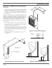
NOTE: If an offset is needed to avoid obstructions, you must support the vent pipe every three (3) feet.
Use wall straps for this purpose. See Figure 28, page 23. Whenever possible, use 45° elbows instead of
90° elbows. The 45° elbow offers less restriction to the fl ow of the fl ue gases and intake air.
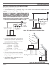
5. Place the flashing over the pipe section(s) extending through the roof. Secure the base of the flashing to the roof
and framing with roofing nails. Be sure roofing material overlaps the top edge of the flashing. There must be a 1"
clearance from the vent pipe to combustible materials.
6. Continue to add pipe sections until the height of the vent cap meets the minimum building code requirements.
NOTE: You must increase vent height for steep roof pitches. Nearby trees, adjoining roof lines, steep
pitched roofs, and other similar factors may cause poor draft or down-drafting in high winds. Increasing
the vent height may solve this problem.
NOTE: If the vent pipe passes through any occupied areas above the fi rst fl oor, including storage spaces and
closets, you must enclose pipe. You may frame and sheetrock
the enclosure with standard construction material. Make sure
to meet the minimum allowable clearances to combustibles. Do
not fi ll any of the required clearance spaces with insulation.
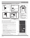
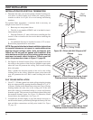
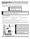
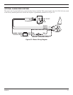
CATHEDRAL CEILING INSTALLATION
1. Remove shingles or other roof covering as necessary to cut the rect-
angular hole for the support box. Mark the outline of the cathedral
ceiling support box on the roof sheathing using the locating hole as
a center point.
2. Cut the hole 1/8" larger than the support box outline. See Figure 32.
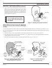
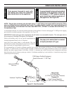
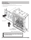
3. Lower the support box through the hole in the roof until the bottom of the box extends at least 2" below the ceiling. See
Figure 32. Align the support box vertically
and horizontally using a level. Temporarily
tack the support box in place through the
inside walls and into the roof sheeting.
4. Using tin snips, cut the support box from the
top corners down to the roof line and fold
the resulting flaps over the roof sheeting.
See Figure 33. Apply a bead of non-hard-
ening, mastic around the top edges of the
support box to make a seal between the
box and the roof. Nail in place with roofing
nails. Remove any combustible material that
might be inside the support box.
5. Complete the cathedral ceiling installation by
following the same procedures outlines in
steps 2 through 6 for Flat Ceiling Installation,
page 24 and above.