


20 54D0700
40
38
36
34
32
30
28
26
24
22
20
18
16
14
12
10
8
6
4
2
2 4 6 8 10 1214 16 1820
eg: A
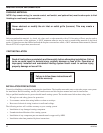
VENT INSTALLATION
HORIZONTAL TERMINATION CONFIGURATIONS
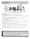
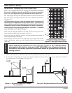
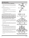
Since it is very important that the venting system maintain its balance
between the combustion air intake and the flue gas exhaust, certain limita-
tions as to vent configurations apply and must be strictly adhered to.
The Vent Graph, showing the relationship between vertical and horizontal
side wall venting, will help to determine the various dimensions allowable.
See Figure 20.
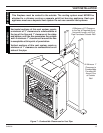
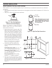
NOTE: Horizontal sections of this vent system require a minimum of 3"
clearances to combustibles at the top of the fl ue and 1" clearance at the
sides and bottom until the fl ue penetrates the outside wall. A minimum 1"
clearance all around the fl ue is acceptable at this point of penetration.
Vertical sections of this vent system require a minimum of 1" clearance
to combustibles on all sides of the pipe.
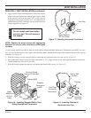
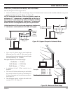
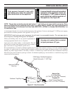
When vent exits through foundations less than 20" below outcrop, the termi-
nation must be flush up with outcropped wall above.
It is best to locate the fireplace in such a way that minimizes the number of
offsets and horizontal vent length.
The horizontal vent run refers to the total length of vent pipe from the flue
collar of the fireplace (or the top of the Transition Elbow) to the face of the
outer wall.
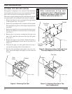
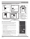
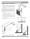
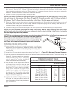
Figure 21 - Maximum Three (3) 90° Elbows
Per Installation
• The maximum number of 90° elbows per side wall installation is three (3). See Figure 21.
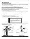
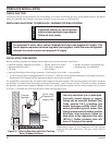
• If a 90° elbow is fitted directly on top of the fireplace flange the maximum horizontal vent run before the termination
or a vertical rise is 36” (914 mm). See Figure 22.
Figure 22 - Maximum Horizontal Run with No Rise
3 x 90°
Elbows
3 x 90°
Elbows
36"
Max.
36"
Max.
Figure 20 - Rear Wall Venting Graph
Horizontal Dimension From the Outside of
Termination to the Back of the Fireplace
Vertical Dimension From the Floor of Unit to the Center of the
Horizontal Vent Pipe
When installing the appliance as a rear vent unit, the 90° or 45° transition elbow
attached directly to the rear of the unit is NOT INCLUDED in the following criteria and
calculations, and unless specifi cally mentioned should be ignored when calculating
venting layouts.
WARNING
20"