


6
Wiring
All field installed wiring must be done in accordance with the
National Electrical Code ANSI/NFPA 70 – Latest Edition or
Canadian Electrical Code CSA C22.1 Part 1 or local codes.
Unit must be electrically grounded according to these codes.
See wiring diagram shipped with unit.
The power to these unit heaters should be protected with a
circuit breaker. Units for use with single-phase electric power,
should be provided with a manual motor starter, having
properly sized overload protection. Units for use with three-
phase electric power must be provided with a motor starter
having properly sized overload protection.
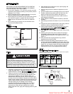
Location of thermostat should be determined by heating
requirements and be mounted on an inside wall about 5' above
floor level where it will not be affected by heat from the unit or
other sources, or drafts from frequently opened doors. See
instructions packed with thermostat.
I
nstallation of Blower Models (BD UNITS)
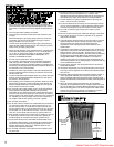
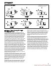
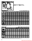
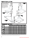
Attachment of Field Installed Ductwork, Blower
(BD) Models Only
Burned-out heat exchanger as well as shorter equipment life
will result from not providing uniform air distribution.
When installing heater always follow good duct design practices
for even distribution of the air across the heat exchanger.
Recommended layouts are shown below.When installing
blower units with ductwork the following must be done.
1.
P
rovide uniform air distribution over the heat exchanger.
Use turning vanes where required. See figures below.
2. Provide removable access panels in the ductwork on the
downstream side of the unit heater. These openings should
be large enough to view smoke or reflect light inside the
casing to indicate leaks in the heat exchanger and to check
for hot spots on exchanger due to poor air distribution or
lack of sufficient air.
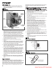
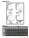
3.
If ductwork is connected to the rear of the unit use Modine
blower enclosure kit or if using field designed enclosure
maintain dimensions of blower enclosure as shown on page 13.
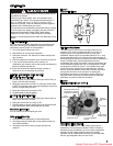
INSTALLATION
CAUTION
Disconnect power supply before making wiring connections
to prevent electrical shock and equipment damage. ALL
UNITS MUST BE WIRED STRICTLY IN ACCORDANCE
WITH WIRING DIAGRAM FURNISHED WITH UNIT.
ANY WIRING DIFFERENT FROM WIRING DIAGRAM MAY
BE HAZARDOUS TO PERSONS AND PROPERTY.
Any damage to or failure of Modine units caused by incorrect
wiring of the units is not covered by MODINE’S STANDARD
WARRANTY (see Back Cover).
CAUTION
Proper air flow and distribution, across the heat exchanger
must be provided to prevent early failure of the blower unit
heater.
CAUTION
Do not attempt to attach ductwork of any kind to propeller PD
models.
CAUTION
Check for red heat exchanger tubes. If bottom of tubes
become red while blower unit is in operation, check for
proper air volume and air distribution. Adjust blower speed or
correct discharge duct design to correct problem.
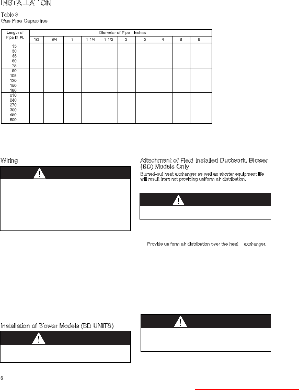
1/2 3/4 1 1 1/4 1 1/2 2 3 4 6 8
15
76 218 440 750 1220 2480 6500 13880 38700 79000
3
0
73 152 285 590 890 1650 4700 9700 27370 55850
45
44 124 260 435 700 1475 3900 7900 23350 45600
60
50 105 190 400 610 1150 3250 6800 19330 39500
75
97 200 345 545 1120 3000 6000 17310 35300
90
88 160 320 490 930 2600 5400 15800 32250
105
80 168 285 450 920 2450 5100 14620 29850
120
158 270 420 860 2300 4800 13680 27920
150
120 242 380 710 2000 4100 12240 25000
180
128 225 350 720 1950 4000 11160 22800
210
205 320 660 1780 3700 10330 21100
240
190 300 620 1680 3490 9600 19740
270
178 285 580 1580 3250 9000 18610
300
170 270 545 1490 3000 8500 17660
450
140 226 450 1230 2500 7000 14420
600
119 192 380 1030 2130 6000 12480
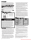
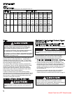
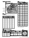
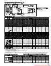
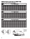
Table 3
Gas Pipe Capacities
In Cu. Ft.per Hour with Pressure Drop pf 0.3 in.W.C. with Specific Gravity 0.60.
Diameter of Pipe - Inches
Length of
Pipe in Ft.
Heater Parts from ACF Greenhouses