


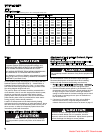
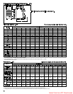
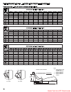
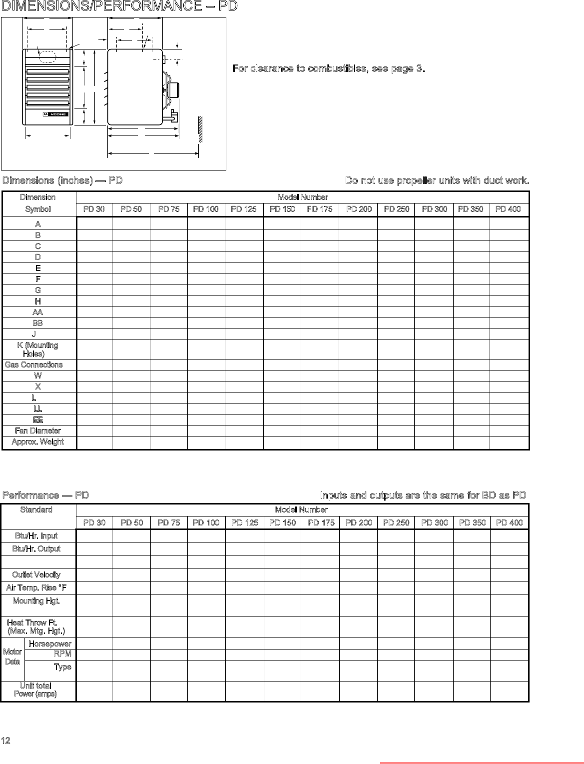
12
Standard Model Number
PD 30 PD 50 PD 75 PD 100 PD 125 PD 150 PD 175 PD 200 PD 250 PD 300 PD 350 PD 400
Btu/Hr. Input
30,000 50,000 75,000 100,000 125,000 150,000 175,000 200,000 250,000 300,000 350,000 400,000
Btu/Hr. Output
24,000 40,000 60,000 80,000 100,000 120,000 140,000 160,000 200,000 240,000 280,000 320,000
Entering Airflow CFM
440 740 1100 1460 1850 2180 2550 2870 3700 4460 4870 5440
Outlet Velocity
515 610 736 860 870 931 959 819 1053 1123 1068 1016
Air Temp. Rise °F
51 50 51 51 50 51 51 52 50 50 53 54
M
ounting Hgt.
(Max.Ft.) ① 7 9 12 14 14 16 17 15 19 21 20 19
H
eat Throw Ft.
①
(Max. Mtg. Hgt.)
25 33 41 49 51 55 59 51 67 74 70 69
Horsepower
1/40 1/40 1/12 1/12 1/8 1/8 1/6 1/6 1/3 1/2 3/4 3/4
RPM
1550 1550 1550 1550 1625 1625 1075 1075 1075 1075 1125 1125
T
ype
Shaded Shaded Shaded Shaded Perm. Perm. Perm. Perm. Perm. Perm. Perm. Perm.
Pole Pole Pole Pole Split Cap. Split Cap. Split Cap. Split Cap. Split Cap. Split Cap. Split Cap. Split Cap.
U
nit total
Power(amps)
1.3 1.3 2.5 2.5 2.6 2.6 3.1 3.1 5.7 7.8 8.3 8.3
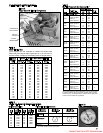
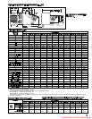
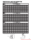
DIMENSIONS/PERFORMANCE – PD
A
H
D (OPENING)
BB
E
AA
B
K
W
X
F
C
K
G
L - Approx
MIN. DISTANCE
TO WALL IS L + 6"
J VENT PIPE
EE
(MIN. DISTANCE TO WALL)
L
LL
Dimensions (inches) — PD Do not use propeller units with duct work.
Performance — PD Inputs and outputs are the same for BD as PD
Dimension Model Number
Symbol PD 30 PD 50 PD75 PD100 PD 125 PD150 PD 175 PD 200 PD 250 PD 300 PD 350 PD 400
A
12-7/8 17-1/4 17-1/4 19-1/4 19-1/4 21 23-1/2 25-5/8 25-5/8 28-5/8 33-5/8 40
B
24-1/4 24-1/4 28-3/4 28-3/4 35-1/4 35-1/4 35-1/4 40-1/4 40-1/4 40-1/4 40-1/4 40-1/4
C
14-3/4 14-3/4 20 20 22 22 22 25 25 25 25 25
D
10-7/16 14-13/16 14-13/16 16-13/16 16-13/16 18-9/16 21-1/16 23-3/16 23-3/16 26-3/16 31-3/16 37-1/2
E
13 13 16 16 20 20 20 24 24 24 24 24
F
9-1/4 9-1/4 11 11 12 12 12 13-1/2 13-1/2 14 – –
G
2 2 2-3/4 2-3/4 3-5/8 3-5/8 3-5/8 4-3/8 4-3/8 4-3/8 4-1/4 4-1/4
H
9-1/4 13-5/8 13-5/8 15-5/8 15-5/8 17-3/8 19-7/8 22 22 25 30 36-3/8
AA
5 5 6-1/4 6-1/4 8 8 8 9 9 9 9 9
BB
6-1/4 6-1/4 6-1/2 6-1/2 7-1/4 7-1/4 7-1/4 7-1/4 7-1/4 7-1/4 7-1/4 7-1/4
J
① 3 4 5 6 6 7 7 7 8 9 10 10
K
(Mounting
3/8-16 3/8-16 3/8-16 3/8-16 3/8-16 3/8-16 3/8-16 3/8-16 3/8-16 3/8-16 3/8-16 3/8-16
Holes)
➂
Gas Connections
➁ 1/2 1/2 1/2 1/2 1/2 1/2 1/2 1/2 1/2 1/2 3/4 3/4
W
– – – – – – – – – – 5 5
X
– – – – – – – – – – 16 16
L
➃ 28-1/4 28-1/4 36 36 36-1/2 37-1/8 37-1/8 40-7/8 41 42-1/4 42-1/4 47-1/4
LL
19-1/2 20-1/8 30 30 30 31-1/8 31-1/8 34-7/8 34-7/8 36-1/4 35-1/2 40-1/2
EE
22-1/4 22-1/4 29 29 30-1/2 30-1/2 30-1/2 32-7/8 32-7/8 32-7/8 32-7/8 32-7/8
Fan Diameter
9 12 12 14 14 16 18 20 20 22 22 24
A
pprox. Weight
58# 72# 102# 116# 152# 162# 169# 231# 231# 261# 330# 410#
Ratings shown are for elevations up to 2,000 ft. For elevations above 2,000 feet, ratings should be reduced at the rate of 4% for each 1,000 feet above sea level. (In Canada see rating plate.)
①
At 65°F ambient and unit fired at full-rated input. Mounting height as measured from bottom of unit, and without deflector hoods.
➁
All single phase motors are totally enclosed and thermal overload protected.Data listed is for standard 115-volt, 60 hertz, single-phase motors.
①
Diameter of round vent pipe to fit oval opening.
➁
For natural gas; may vary depending on control availability.
➂
PD 30 through PD 300 — 2 holes (and the level hanging adjustment feature).PD 350 through PD 400 — 4 holes.
➃
Dimension equals overall plus 6".
Motor
Data
➁
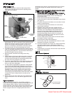
For clearance to combustibles, see page 3.
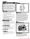
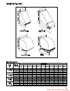
Heater Parts from ACF Greenhouses