


5
ADDITIONAL VENTING REQUIREMENTS FOR VENTING
INTO AN EXISTING MASONRY CHIMNEY OR COMMON
VENT (CATEGORY I and II UNITS ONLY)
1. Do not vent a Category I or II unit into a common vent with
mechanical draft systems operating under positive pressure
(Category III or IV units).
2. When connecting vent to an existing chimney, do not push
vent pipe beyond internal surface of chimney.
3. When venting into a common vent, the area of the common
vent should be equal to or greater than the area of the
largest vent plus 50 percent of the area of all additional
vents.
4. When venting into a common vent, the individual vents
should enter at different levels.
P
iping
1. Installation of piping must be in accordance with local
codes, and ANSI Z223.1, “National Fuel Gas Code,” or
CAN/CGA-B149 in Canada.
D
o not use flexible connectors
.
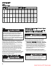
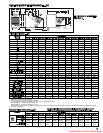
2. Piping to units should conform with local and national
requirements for type and volume and gas handled, and
pressure drop allowed in the line. Refer to Table 4, to
determine the cubic feet per hour (cfh) for the type of gas
and size of unit to be installed. Using this cfh value and the
length of pipe necessary, determine the pipe diameter from
Table 3. Where several units are served by the same main,
the total capacity, cfh, and length of main must be
considered. Avoid pipe sizes smaller than 1/2”. Table 3
allows for the usual number of fittings with a 0.3” W.C.
pressure drop. Where the gas supplied has a specific
gravity other than 0.60, apply the multiplying factor as given
in Table 2.
3. After threading and reaming the ends, inspect piping and
remove loose dirt and chips.
4. Support piping so that no strains are imposed on unit or
controls.
5. Use two wrenches when connecting piping to unit controls.
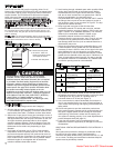
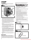
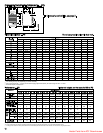
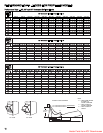
6. Provide a sediment trap before each unit and in the line
where low spots cannot be avoided. (See Figure 4).
7. Take-off to unit should come from top or side of main to
avoid trapping condensate.
8. Piping, subject to wide temperature variations, should be
insulated.
9. Pitch piping up toward unit at least 1/4” per 15’ of horizontal
run.
10. Compounds used on threaded joints of gas piping must be
resistant to action of liquefied petroleum gases.
11. Purge air before lighting unit by disconnecting pilot tubing
at combination gas control.
I
n no case should line be
purged into heat exchanger.
12. After installation, check system for gas leaks, using a soap
solution.
13. Install a ground joint union and a manual shut off valve
immediately upstream of the unit including a 1/8” NPT
plugged tapping accessible for test gage connection. (See
Figure 4).
14. Allow at least 5 feet of piping between any pressure
regulator and unit control string.
15. When Pressure/Leak testing, pressures above 14'' W.C.
(1/2 psi), close the field installed shut-off valve, disconnect
the appliance and its combination gas control from the gas
supply line, and plug the supply line before testing. When
testing pressures 14" W.C. (1/2 psi) or below, close the
manual shut-off valve on the appliance before testing.
GAS
SUPPLY LINE
GAS
SUPPLY LINE
GROUND
JOINT
UNION
MANUAL
SHUT-OFF
VALVE
3"
MIN.
SEDIMENT
TRAP
PLUGGED
1/8" NPT TEST
GAGE CONNECTION
TO
CONTROLS
CAUTION
Gas pressure to unit heater controls must never exceed 14"
W.C. (1/2 psi).
When leak testing the gas supply piping system, the
appliance and its combination gas control must be isolated
during any pressure testing in excess of 14" W.C. (1/2 psi).
The appliance should be isolated from the gas supply piping
system by closing its field installed manual shut-off valve
during any pressure testing of the gas supply piping system.
INSTALLATION
Figure 4
Recommended Piping to Controls
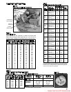
Table 2
Specific Gravity Conversion Factors
Multiplying factors to be used with Table 3 cubic ft./hr.values when the specific
gravity of gas is other than 0.60.
N
ATURAL GAS
Specific
Gravity Factor
0.55 1.04
0.60 1.00
0.65 0.962
PROPANE GAS
Specific
Gravity Factor
1.50 0.633
1.53 0.626
1.60 0.612
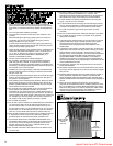
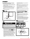
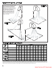
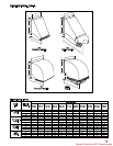
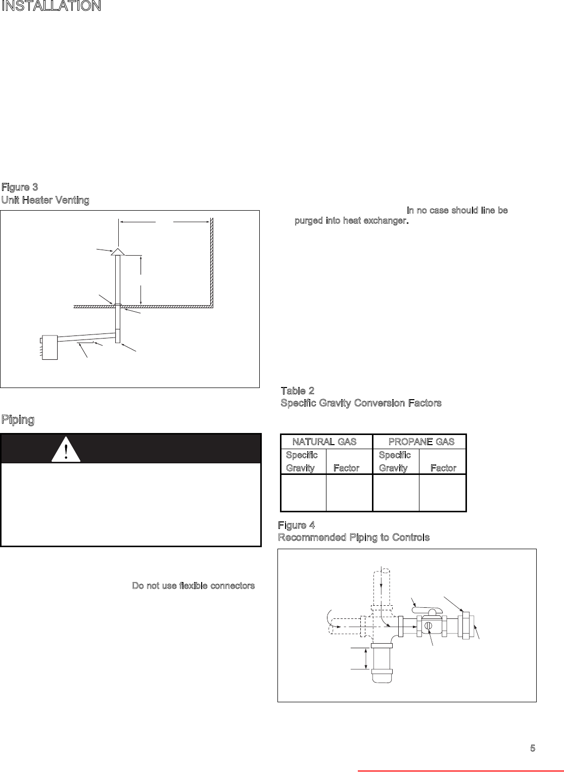
10' MIN.
TO WALL OR ADJOINING BUILDING
2'
MIN.
ROOF FLASHING
USE THIMBLE
THROUGH CEILING
APPROVED
TERMINAL
1'0"
SLOPE 1/4" TO
THE FOOT
UNIT
1/4"
DRIP LEG WITH
CLEANOUT CAP
*SIZE ACCORDING TO EXPECTED SNOW DEPTH.
*
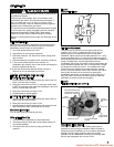
Figure 3
Unit Heater Venting
Heater Parts from ACF Greenhouses