


- 36 -
[ II Restrictions ]
GBHWE09120
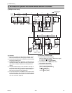
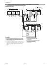
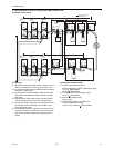
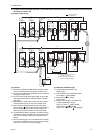
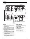
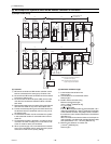
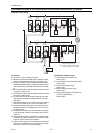
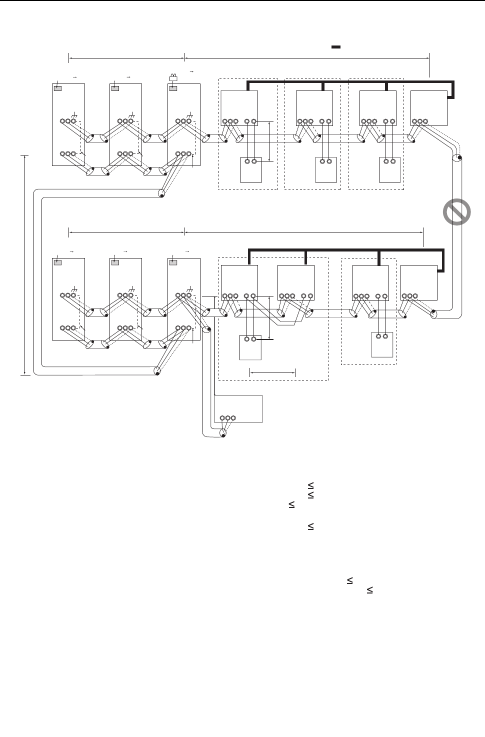
5. An example of a system in which a system controller is connected to the indoor-outdoor transmission line (except
LM adapter)
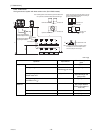
(1) Sample control wiring
(2) Cautions
1) ME remote controller and MA remote controller cannot
both be connected to the same group of indoor units.
2) No more than 2 MA remote controllers can be connected
to a group of indoor units.
3) Do not connect the terminal blocks (TB5) on the indoor
units that are connected to different outdoor units with
each other.
4) Replacement of male power jumper connector (CN41)
must be performed only on one of the outdoor units.
5) Provide grounding to S terminal on the terminal block for
transmission line for centralized control (TB7) on only
one of the outdoor units.
6) A maximum of 3 system controllers can be connected to
the indoor-outdoor transmission line, with the exception
that only one G(B)-50A may be connected.
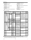
7) When the total number of indoor units exceeds 26, it may
not be possible to connect a system controller on the in-
door-outdoor transmission line.
8) In a system to which more than 18 indoor units including
one or more indoor units of 72 model or above are con-
nected, there may be cases in which the system control-
ler cannot be connected to the indoor-outdoor
transmission line.
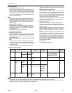
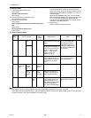
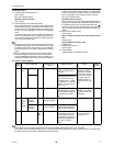
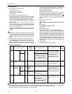
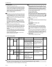
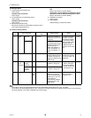
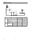
(3) Maximum allowable length
1) Indoor/outdoor transmission line
Maximum distance (1.25mm
2
[AWG16] or larger)
L11+L12 200m [656ft]
L21+L22 200m [656ft]
L25 200m [656ft]
2) Transmission line for centralized control
L31+L21 200m [656ft]
3) MA remote controller wiring
Same as [5] 1.
4) Maximum line distance via outdoor unit
(1.25mm
2
[AWG16] or larger)
L25+L31+L12(L11) 500m [1640ft]
L12(L11)+L31+L22(L21) 500m [1640ft]
IC
TB5
S
TB
15
1 2
01
IC
TB5
S
TB
15
1 2
02
A B
MA
A B
MA
LC
TB5
S
07
IC
TB5
S
1 2
TB
15
IC
TB5
S
TB
15
1 2
05 04
LC
TB5
S
08
IC
TB5
S
TB
15
1 2
03
A B
MA
IC
TB5
S
TB
15
1 2
06
A B
MA
A B
MA
M1 M2 M1 M2 M1 M2 M1 M2
M1 M2
M1 M2
M1 M2 M1 M2
L12 L11
L22 L21
m3
OC
TB3
TB7
S
51
m2 m1
OS1
TB3
TB7
S
52
OS2
TB3
TB7
M1 M2 M1 M2 M1 M2
M1 M2 M1 M2 M1 M2
S
53
OC
TB3
TB7
S
54
OS1
TB3
TB7
S
55
OS2
TB3
TB7
M1 M2 M1 M2 M1 M2
M1 M2 M1 M2 M1 M2
S
56
L31
A B S
L25
Note1 LM adapters cannot be connected to the
indoor-outdoor transmission line.
Note1
System controller
SW2-1 OFF ON
SW2-1 OFF ON
Leave the male
connector on
CN41 as it is.
SW2-1 OFF ON
Leave the male
connector on
CN41 as it is.
Move the male connector
from CN41 to CN40.
SW2-1 OFF ON
Leave the male
connector on
CN41 as it is.
SW2-1 OFF ON
Leave the male
connector on
CN41 as it is.
SW2-1 OFF ON
Leave the male
connector on
CN41 as it is.
Group Group Group
Group Group
Interlock operation with
the ventilation unit
To be left
unconnected
To be left
unconnected
To be left
unconnected
To be left
unconnected
To be left
unconnected
To be connected