


[ IX Troubleshooting ]
- 270 -
HWE09120 GB
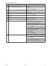
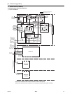
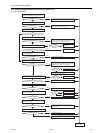
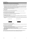
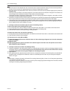
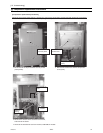
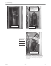
(2) Troubleshooting transmission power circuit of outdoor unit
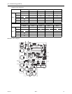
1) PUHY-P72TJMU-A
Check the voltage between No.1 and No.2 pins of the
CNS2 on the control board.
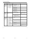
Check the wiring between the control board and power
supply board for the transmission line (CN102 and CNIT),
and check for proper connection of connectors.
Check the wiring between the control board and power
supply board for the transmission line (CN102 and CNIT),
and check for proper connection of connectors.
Is there a wiring
error or a connector
disconnection?
Check the voltage between No.5 and No.2 pins
of the CNIT on the control board.
Is the voltage
measurement between
4.5 and 5.2 VDC?
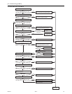
Is there a connector
disconnection?
Fix the connector disconnection.
Replace the M-NET board
Replace the M-NET board
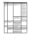
Replace the inrush current
limiting resistor.
Replace the INV board.
Replace the INV board.
Check the wiring between the noise filter and the
INV board as well as screw tightness, and fix any
problems found.
Replace the noise filter.
Check and fix any power supply wiring and main power
supply problems found.
Check the inrush current resistance (R1).
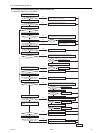
Fix the wiring and connector
disconnection.
Check for shorted transmission
line for centralized control.
Replace the control board.
Check the voltage between No.1 and No.2 pins of the
CN102 on the power supply board for the transmission line.
Check the voltage between No.1 and No.3 pins of
the CNDC on the INV board.
Check the voltage between SC-P1 and TB-N on the INV board.
Check the voltages among SC-R, SC-S, and
SC-T on the INV board.
Check the voltages among TB21, TB22, and
TB23 on the noise filter.
Check the voltage at the power supply terminal block TB1.
DC24
~
30V
DC24
~
30V
DC24
~
30V
DC265
~
357V
DC265
~
357V
AC188
~
253V
AC188
~
253V
AC188
~
253V
DC24
~
30V
Turn on the
power again.
YES
YES
YES
YES
YES
YES
YES
YES
YES
YES
YES
YES
YES
YES
YES
YES
NO
NO
NO
NO
NO
NO
NO
NO
NO
NO
NO
NO
NO
NO
NO
NO
22 10%
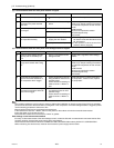
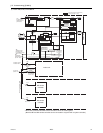
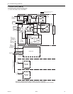
Check the voltage at the indoor/outdoor
transmission terminal block (TB3) of outdoor unit.
DC 24 ~ 30 V
DC 24 ~ 30 V
Check the voltage at TB3 after removing transmission line from TB3.
Check whether the male connector is connected to
the female power supply connector (CN40).
Connected
Check voltage of terminal block for centralized control (TB7).
Check voltage of TB7 by removing transmission line from TB7.
Check if the indoor/outdoor transmission line is not
short-circuited, and repair the problem.
Check whether the transmission line is disconnected,
check for contact failure, and repair the problem.
[TJMU-A]