


S1
S2
S3
S1
S2
S3
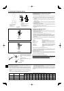
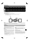
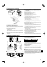
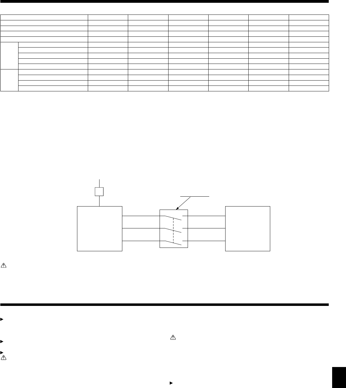
208/230V
Single phase
Isolator
3 poles isolator
A-Control
Outdoor Unit
A-Control
Indoor Unit
9
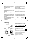
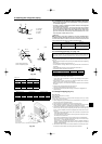
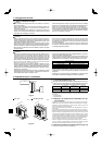
6. Electrical work
Warning:
In case of A-control wiring, there is high voltage potential on the S3 terminal caused by electrical circuit design that has no electrical insulation between power
line and communication signal line. Therefore, please turn off the main power supply when servicing. And do not touch the S1, S2, S3 terminals when the power
is energized. If isolator should be used between indoor unit and outdoor unit, please use 3-pole type.
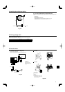
7. Test run
7.1. Before test run
After completing installation and the wiring and piping of the indoor and
outdoor units, check for refrigerant leakage, looseness in the power supply
or control wiring, wrong polarity, and no disconnection of one phase in the
supply.
Use a 500-volt megohmmeter to check that the resistance between the
power supply terminals and ground is at least 1.0M.
Do not carry out this test on the control wiring (low voltage circuit) terminals.
Warning:
Do not use the air conditioner if the insulation resistance is less than 1.0M.
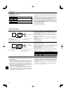
Insulation resistance
After installation or after the power source to the unit has been cut for an extended
period, the insulation resistance will drop below 1 MΩ due to refrigerant accumulat-
ing in the compressor. This is not a malfunction. Perform the following procedures.
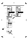
1. Remove the wires from the compressor and measure the insulation resistance of
the compressor.
2. If the insulation resistance is below 1 MΩ, the compressor is faulty or the resis-
tance dropped due the accumulation of refrigerant in the compressor.
3. After connecting the wires to the compressor, the compressor will start to warm
up after power is supplied. After supplying power for the times indicated below,
measure the insulation resistance again.
• The insulation resistance drops due to accumulation of refrigerant in the com-
pressor. The resistance will rise above 1 MΩ after the compressor is warmed
up for two to three hours.
(The time necessary to warm up the compressor varies according to atmo-
spheric conditions and refrigerant accumulation.)
• To operate the compressor with refrigerant accumulated in the compressor, the
compressor must be warmed up at least 12 hours to prevent breakdown.
4. If the insulation resistance rises above 1 MΩ, the compressor is not faulty.
Caution:
• The compressor will not operate unless the power supply phase connection
is correct.
• Turn on the power at least 12 hours before starting operation.
- Starting operation immediately after turning on the main power switch can result
in severe damage to internal parts. Keep the power switch turned on during the
operational season.
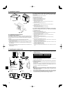
The followings must be checked as well.
• The outdoor unit is not faulty. LED1 and LED2 on the control board of the outdoor
unit fl ash when the outdoor unit is faulty.
• Both the gas and liquid stop valves are completely open.
•
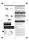
A protective sheet covers the surface of the DIP switch panel on the control board of
the outdoor unit. Remove the protective sheet to operate the DIP switches easily.
• Make sure that the all of the SW5 DIP switches for function changes on the con-
trol board of the outdoor unit are set to OFF. If all of the SW5 switches are not set
to OFF, record the settings and then set all of the switches to OFF. Begin recov-
ering the refrigerant. After moving the unit to a new location and completing the
test run, set the SW5 switches to the previously recorded settings.
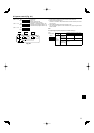
6.2. Field electrical wiring
Outdoor unit model A12 A18 A24 A30 A36 A42
Outdoor unit power supply
Single, 208/230 V, 60 Hz Single, 208/230 V, 60 Hz Single, 208/230 V, 60 Hz Single, 208/230 V, 60 Hz Single, 208/230 V, 60 Hz Single, 208/230 V, 60 Hz
Breaker size *4 15 A 15 A 25 A 30 A 30 A 30 A
Minimum circuit ampacity 13 A 13 A 18 A 25 A 25 A 26 A
Maximum rating of overcurrent protective device 15 A 20 A 30 A 40 A 40 A 40 A
Wiring
Wire No. ×
size
Outdoor unit power supply 2 × Min. AWG 14 2 × Min. AWG 14 2 × Min. AWG 12 2 × Min. AWG 10 2 × Min. AWG 10 2 × Min. AWG 10
Outdoor unit power supply earth 1 × Min. AWG 14 1 × Min. AWG 14 1 × Min. AWG 12 1 × Min. AWG 10 1 × Min. AWG 10 1 × Min. AWG 10
Indoor unit-Outdoor unit *1 3 × AWG 16 (polar) 3 × AWG 16 (polar) 3 × AWG 16 (polar) 3 × AWG 16 (polar) 3 × AWG 16 (polar) 3 × AWG 16 (polar)
Indoor unit earth *1 1 × Min. AWG 16 1 × Min. AWG 16 1 × Min. AWG 16 1 × Min. AWG 16 1 × Min. AWG 16 1 × Min. AWG 16
Remote controller-Indoor unit *2
2 × AWG 22 (Non-polar) 2 × AWG 22 (Non-polar) 2 × AWG 22 (Non-polar) 2 × AWG 22 (Non-polar) 2 × AWG 22 (Non-polar) 2 × AWG 22 (Non-polar)
Circuit
rating
Outdoor unit L1-L2 *3 AC 208/230 V AC 208/230 V AC 208/230 V AC 208/230 V AC 208/230 V AC 208/230 V
Indoor unit-Outdoor unit S1-S2 *3 AC 208/230 V AC 208/230 V AC 208/230 V AC 208/230 V AC 208/230 V AC 208/230 V
Indoor unit-Outdoor unit S2-S3 *3 DC 24 V DC 24 V DC 24 V DC 24 V DC 24 V DC 24 V
Remote controller-Indoor unit *3 DC 12 V DC 12 V DC 12 V DC 12 V DC 12 V DC 12 V
*1. Max. 45 m, 147 ft
If 2.5 mm
2
used, Max. 50 m, 164 ft
If 2.5 mm
2
used and S3 separated, Max. 80 m, 262ft
*2. The 10 m, 30 ft wire is attached in the remote controller accessory. Max 1500 ft
*3. The fi gures are NOT always against the ground.
S3 terminal has DC 24 V against S2 terminal. However between S3 and S1, these terminals are NOT electrically insulataed by the transformer or other device.
*4. Use earth leakage breaker (NV)
Notes: 1. Wiring size must comply with the applicable local and national code.
2.
Use copper supply wires.
3. Use wires rated 600V or more for the power supply cables and the indoor/outdoor unit connecting cables.
4. Install an earth longer than other cables.