


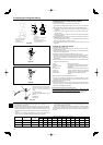
31-1/2
11-13/16+29/32
23-5/8
5-29/32
2-23/32
19-11/16
13
37-13/32
13+1-3/16
37-1/8(53-5/32)
6-7/8
23-5/8
14-9/16
3
1. Safety precautions
1.3. Before electric work
Caution:
• Be sure to install circuit breakers. If not installed, electric shock may result.
• For the power lines, use standard cables of suffi cient capacity. Otherwise, a
short circuit, overheating, or fi re may result.
• When installing the power lines, do not apply tension to the cables. If the
connections are loosened, the cables can snap or break and overheating or
fi re may result.
• Be sure to ground the unit. Do not connect the ground wire to gas or water
pipes, lighting rods, or telephone grounding lines. If the unit is not properly
grounded, electric shock may result.
• Use circuit breakers (ground fault interrupter, isolating switch (+B fuse),
and molded case circuit breaker) with the specifi ed capacity. If the circuit
breaker capacity is larger than the specified capacity, breakdown or fire
may result.
1.4. Before starting the test run
Caution:
• Turn on the main power switch more than 12 hours before starting opera-
tion. Starting operation just after turning on the power switch can severely
damage the internal parts. Keep the main power switch turned on during
the operation season.
• Before starting operation, check that all panels, guards and other protective
parts are correctly installed. Rotating, hot, or high voltage parts can cause
injuries.
• Do not touch any switch with wet hands. Electric shock may result.
• Do not touch the refrigerant pipes with bare hands during operation. The
refrigerant pipes are hot or cold depending on the condition of the fl owing
refrigerant. If you touch the pipes, burns or frostbite may result.
• After stopping operation, be sure to wait at least fi ve minutes before turn-
ing off the main power switch. Otherwise, water leakage or breakdown may
result.
1.5. Using R410A refrigerant air conditioners
Caution:
• Use C1220 copper phosphorus, for copper and copper alloy seamless
pipes, to connect the refrigerant pipes. Make sure the insides of the pipes
are clean and do not contain any harmful contaminants such as sulfuric
compounds, oxidants, debris, or dust. Use pipes with the specifi ed thick-
ness. (Refer to page 5) Note the following if reusing existing pipes that car-
ried R22 refrigerant.
- Replace the existing fl are nuts and fl are the fl ared sections again.
- Do not use thin pipes. (Refer to page 5)
• Store the pipes to be used during installation indoors and keep both ends
of the pipes sealed until just before brazing. (Leave elbow joints, etc. in
their packaging.) If dust, debris, or moisture enters the refrigerant lines, oil
deterioration or compressor breakdown may result.
• Use ester oil, ether oil, alkylbenzene oil (small amount) as the refrigeration
oil applied to the fl ared sections. If mineral oil is mixed in the refrigeration
oil, oil deterioration may result.
• Do not use refrigerant other than R410A refrigerant. If another refrigerant is
used, the chlorine will cause the oil to deteriorate.
• Use the following tools specifi cally designed for use with R410A refrigerant.
The following tools are necessary to use R410A refrigerant. Contact your
nearest dealer for any questions.
Tools (for R410A)
Gauge manifold Flare tool
Charge hose Size adjustment gauge
Gas leak detector Vacuum pump adapter
Torque wrench Electronic refrigerant charging scale
• Be sure to use the correct tools. If dust, debris, or moisture enters the re-
frigerant lines, refrigeration oil deterioration may result.
• Do not use a charging cylinder. If a charging cylinder is used, the composi-
tion of the refrigerant will change and the effi ciency will be lowered.
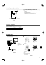
2. Installation location
Fig. 2-2
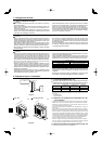
A12, A18
Fig. 2-1
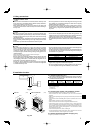
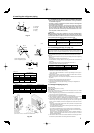
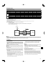
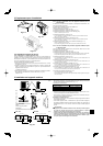
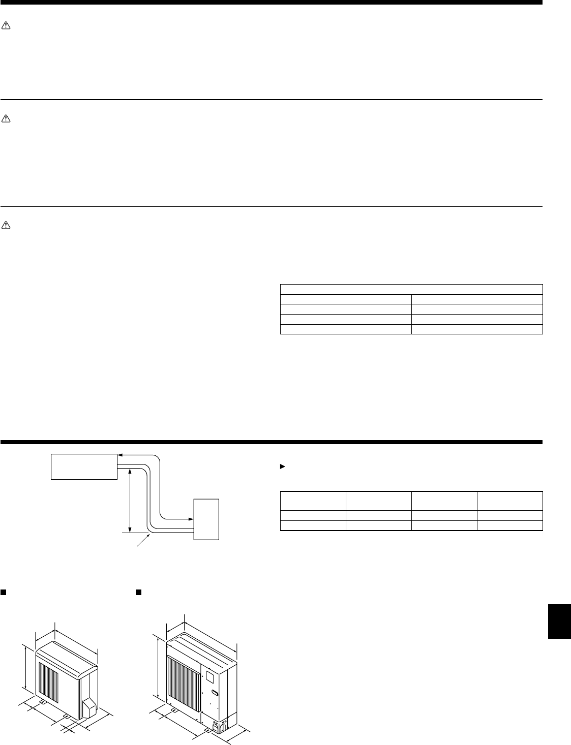
2.1. Refrigerant pipe (Fig. 2-1)
Check that the difference between the heights of the indoor and outdoor
units, the length of refrigerant pipe, and the number of bends in the pipe
are within the limits shown below.
Models
APipe length
(one way)
BHeight
difference
C
Number of
bends (one way)
A12, A18 Max. 30 m, 100 ft Max. 30 m,100 ft Max. 15
A24,A30,A36,A42 Max. 50 m, 165 ft Max. 30 m,100 ft Max. 15
• Height difference limitations are binding regardless of which unit, indoor or out-
door, is positioned higher.
D
Indoor unit
E
Outdoor unit
2.2. Choosing the outdoor unit installation location
• Avoid locations exposed to direct sunlight or other sources of heat.
• Select a location from which noise emitted by the unit will not inconvenience
neighbors.
• Select a location permitting easy wiring and pipe access to the power source and
indoor unit.
• Avoid locations where combustible gases may leak, be produced, fl ow, or accu-
mulate.
• Note that water may drain from the unit during operation.
• Select a level location that can bear the weight and vibration of the unit.
• Avoid locations where the unit can be covered by snow. In areas where heavy
snow fall is anticipated, special precautions such as raising the installation loca-
tion or installing a hood on the air intake must be taken to prevent the snow from
blocking the air intake or blowing directly against it. This can reduce the airfl ow
and a malfunction may result.
• Avoid locations exposed to oil, steam, or sulfuric gas.
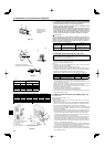
• Use the transportation handles of the outdoor unit to transport the unit. If the unit
is carried from the bottom, hands or fi ngers may be pinched.
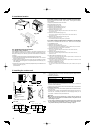
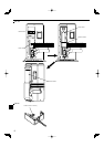
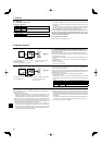
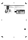
2.3. Outline dimensions (Outdoor unit) (Fig. 2-2)
The fi gure in parenthesis is for A42 model.
A
B
E
D
C
(inch) (inch)
A24, A30, A36, A42