


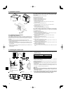
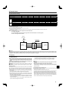
Fig. 3-1
Max. 23/32 for A12, A18
Max. 1-3/16 for A24-A42
A24-A42A12, A18
A24-A42A12, A18
19-11/16 19-11/16
Min. 25-19/32
5-29/32 5-29/32
Min. 13-25/32
31-1/2
1-9/32
11-13/16
13
23-5/8 23-5/8
Min. 14-3/16
6-7/8 6-7/8
Min. 13/32
37-13/32
1-3/32
13
14-9/16
(inch)
(inch)
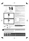
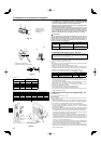
M10(3/8”)bolt
Base
As long as possible.
Vent
Set deep in the ground.
4
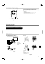
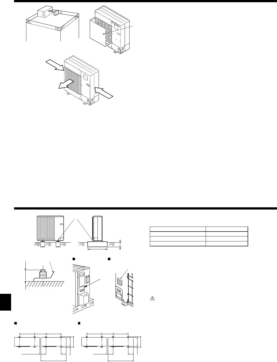
2. Installation location
2.4. Ventilation and service space
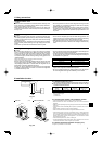
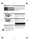
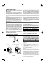
2.4.1. Windy location installation
When installing the outdoor unit on a rooftop or other location unprotected from the
wind, situate the air outlet of the unit so that it is not directly exposed to strong winds.
Strong wind entering the air outlet may impede the normal airfl ow and a malfunction
may result.
The following shows three examples of precautions against strong winds.
1 Face the air outlet towards the nearest available wall about 50 cm, 19-11/16 inch
away from the wall. (Fig. 2-3)
2
Install an optional air outlet guide and air guide if the unit is installed in a location
where strong winds from a typhoon, etc. may directly enter the air outlet. (Fig. 2-4)
AAir outlet guide
3 Position the unit so that the air outlet blows perpendicularly to the seasonal wind
direction, if possible. (Fig. 2-5)
B Wind direction
Fig. 2-4
Fig. 2-3
A
B
Fig. 2-5
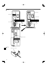
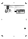
2.4.2. When installing a single outdoor unit (Refer to the last page)
Minimum dimensions are as follows, except for Max., meaning Maximum dimen-
sions, indicated.
The fi gures in parentheses are for A42 models.
Refer to the fi gures for each case.
1 Obstacles at rear only (Fig. 2-6)
2 Obstacles at rear and above only (Fig. 2-7)
3 Obstacles at rear and sides only (Fig. 2-8)
*
350mm, 13-25/32 inch for A12, A18
4 Obstacles at front only (Fig. 2-9)
*
When using an optional air outlet guide, the clearance for A42 models is 500 mm,
19-11/16 inch or more.
5 Obstacles at front and rear only (Fig. 2-10)
*
When using an optional air outlet guide, the clearance for A42 models is 500 mm,
19-11/16 inch or more.
6 Obstacles at rear, sides, and above only (Fig. 2-11)
*
350mm, 13-25/32 inch for A12, A18
• Do not install the optional air outlet guides for upward airfl ow.
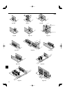
2.4.3. When installing multiple outdoor units (Refer to the last page)
Leave 350 mm, 13-25/32 inch for A18 and 10 mm, 13/32 inch for A24-A42 space
or more between the units.
1 Obstacles at rear only (Fig. 2-12)
2 Obstacles at rear and above only (Fig. 2-13)
• No more than three units must be installed side by side. In addition, leave space as shown.
• Do not install the optional air outlet guides for upward airfl ow.
3 Obstacles at front only (Fig. 2-14)
*
When using an optional air outlet guide, the clearance for A42 models is 1000 mm,
39-3/8 inch or more.
4 Obstacles at front and rear only (Fig. 2-15)
*
When using an optional air outlet guide, the clearance for A42 models is 1000 mm,
39-3/8 inch or more.
5 Single parallel unit arrangement (Fig. 2-16)
*
When using an optional air outlet guide installed for upward airfl ow, the clearance is 500
(1000) mm, 19-11/16 (39-3/8) inch or more.
6 Multiple parallel unit arrangement (Fig. 2-17)
*
When using an optional air outlet guide installed for upward airfl ow, the clearance is 1000
(1500) mm, 39-3/8 (59-1/16) inch or more.
7 Stacked unit arrangement (Fig. 2-18)
• The units can be stacked up to 2 units high.
• No more than two stacked units must be installed side by side. In addition, leave space as
shown.
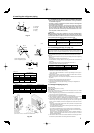
3. Installing the outdoor unit
• Be sure to install the unit in a sturdy, level surface to prevent rattling noises dur-
ing peration. (Fig. 3-1)
<Foundation specifi cations>
Foundation bolt M10 (3/8")
Thickness of concrete 120 mm, 4-23/32 inch
Length of bolt 70 mm, 2-3/4 inch
Weight-bearing capacity 320 kg, 264 lbs
• Make sure that the length of the foundation bolt is within 30 mm, 1-3/16 inch of
the bottom surface of the base.
•
Secure the base of the unit fi rmly with four-M10 foundation bolts in sturdy locations.
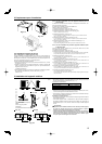
Installing the outdoor unit
• Do not block the vent. If the vent is blocked, operation will be hindered and break-
down may result.
• In addition to the unit base, use the installation holes on the back of the unit to at-
tach wires, etc., if necessary to install the unit. Use self-tapping screws (ø5 × 15
mm, ø13/16 × 19/32 inch or less) and install on site.
Warning:
• The unit must be securely installed on a structure that can sustain its
weight. If the unit is mounted on an unstable structure, it may fall down and
cause damage or injuries.
• The unit must be installed according to the instructions in order to minimize
the risk of damage from earthquakes, typhoons, or strong winds. An incor-
rectly installed unit may fall down and cause damage or injuries.