


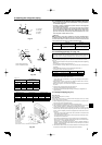
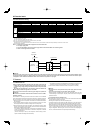
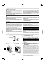
Flare cutting dimensions
45˚± 2˚
90˚± 0.5˚
Flare nut tightening torque
ø
A
R1/64
to R1/32
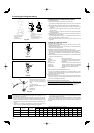
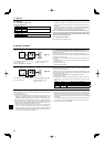
Fig. 4-2
(inch)
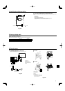
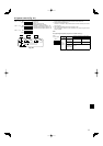
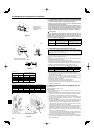
Fig. 4-3
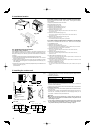
Front piping cover
Piping cover
Stop valve
Service panel
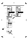
Bend radius : 100 mm, 3-15/16 inch-150 mm, 5-27/32 inch
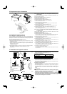
A24-A42A12, A18
A Liquid pipe
B Gas pipe
C Inslation
D Taping
5
4. Installing the refrigerant piping
4.1.
Precautions for devices that use R410A refrigerant
• Refer to page 3 for precautions not included below on using air condition-
ers with R410A refrigerant.
• Use ester oil, ether oil, alkylbenzene oil (small amount) as the refrigeration
oil applied to the fl ared sections.
• Use C1220 copper phosphorus, for copper and copper alloy seamless
pipes, to connect the refrigerant pipes. Use refrigerant pipes with the thick-
nesses specified in the table to the below. Make sure the insides of the
pipes are clean and do not contain any harmful contaminants such as sul-
furic compounds, oxidants, debris, or dust.
Warning:
When installing or moving the air conditioner, use only the specifi ed refriger-
ant (R410A) to charge the refrigerant lines. Do not mix it with any other refrig-
erant and do not allow air to remain in the lines. Air enclosed in the lines can
cause pressure peaks resulting in a rupture and other hazards.
A12, A18 A24-A42
Liquid pipe
ø6.35 mm, 1/4inch
thickness 0.8 mm, 1/32 inch
ø9.52 mm, 3/8 inch
thickness 0.8 mm, 1/32 inch
Gas pipe
ø12.7 mm, 1/2 inch
thickness 0.8 mm, 1/32 inch
ø15.88 mm, 5/8 inch
thickness 1.0 mm, 3/64 inch
• Do not use pipes thinner than those specifi ed above.
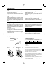
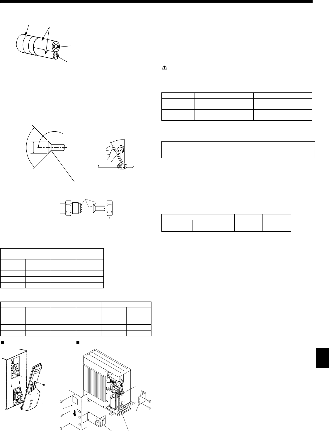
4.2. Connecting pipes (Fig. 4-1) (Fig. 4-2)
When commercially available copper pipes are used, inslate both the liquid and
gas pipes separately with commercially available insulation materials (heat-resis-
tant to 100 °C, 212 °F or more, thickness of 12 mm, 1/2 inch or more). (Fig. 4-1)
•
The indoor parts of the drain pipe should be wrapped with polyethylene foam insu-
lation materials (specifi c gravity of 0.03, thickness of 9 mm, 23/64 inch or more).
[Fig. 4-2]
• Apply thin layer of refrigerant oil to pipe and joint seating surface before tightening
fl are nut. A
• Use 2 wrenches to tighten piping connections. B
• Use leak detector or soapy water to check for gas leaks after connections are
completed.
• Apply refrigerating machine oil over the entire fl are seat surface. C
• Use the fl are nuts for the following pipe size. D
A12, A18 A24 - A42
Gas side Pipe size (mm, inch) ø12.7, 1/2” ø15.88, 5/8”
Liquid side Pipe size (mm, inch) ø6.35, 1/4” ø9.52, 3/8”
*1: The fl are nut is attached to its pipe.
*2: The fl are nut is in the outdoor unit accessory.
Do not use the fl are nut attached. If it is used, a gas leakage or even a pipe ex-
traction may occur.
• When bending the pipes, be careful not to break them. Bend radii of 100 mm,
3-15/16 inch to 150 mm, 5-27/32 inch are suffi cient.
• Make sure the pipes do not contact the compressor. Abnormal noise or vibration
may result.
1 Pipes must be connected starting from the indoor unit.
Flare nuts must be tightened with a torque wrench.
2 Flare the liquid pipes and gas pipes and apply a thin layer of refrigeration oil
(Applied on site).
4.3. Refrigerant piping (Fig. 4-3)
For A12, A18
Remove the service panel D (1 screw).
For A24-A42
Remove the service panel D (3 screws) and the front piping cover A (2 screws)
and rear piping cover B (2 screws).
1 Perform refrigerant piping connections for the indoor/outdoor unit when the out-
door unit’s stop valve is completely closed.
2 Vacuum-purge air from the indoor unit and the connection piping.
3 After connecting the refrigerant pipes, check the connected pipes and the indoor
unit for gas leaks. (Refer to 4.4 Refrigerant pipe airtight testing method)
4 Vacuumize the refrigerant lines through the service port of the liquid stop valve
and then open the stop valves completely (for both the liquid and gas stop
valves). This will completely connect the refrigerant lines of the indoor and out-
door units.
• If the stop valves are left closed and the unit is operated, the compressor and
control valves will be damaged.
• Use a leak detector or soapy water to check for gas leaks at the pipe connec-
tion sections of the outdoor unit.
• Do not use the refrigerant from the unit to purge air from the refrigerant lines.
• After the valve work is completed, tighten the valve caps to the correct torque:
20 to 25 N·m, 14 to 18 ft·lbs (200 to 250 kgf·cm).
Failure to replace and tighten the caps may result in refrigerant leakage. In
addition, do not damage the insides of the valve caps as they act as a seal to
prevent refrigerant leakage.
5 Use sealant to seal the ends of the thermal insulation around the pipe connec-
tion sections to prevent water from entering the thermal insulation.
A (Fig. 4-1)
Copper pipe O.D.
Flare dimensions
øA dimensions
(mm) (inch) (mm) (inch)
ø6.35 1/4” 8.7 - 9.1 11/32 - 23/64
ø9.52 3/8” 12.8 - 13.2 1/2 - 33/64
ø12.7 1/2” 16.2 - 16.6 41/64 - 21/32
ø15.88 5/8” 19.3 - 19.7 49/64 - 25/32
B (Fig. 4-1)
Copper pipe O.D. Flare nut O.D. Tightening torque
(mm) (inch) (mm) (inch) (N·m) (ft·lbs)
ø6.35 1/4” 17 43/64 14 - 18 10 - 13
ø9.52 3/8” 22 7/8 34 - 42 25 - 30
ø12.7 1/2” 26 1 - 3/64 49 - 61 35 - 44
ø15.88 5/8” 29 1 - 9/64 68 - 82 49 - 59
Fig. 4-1