


10
8. Special Functions
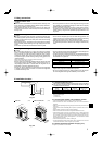
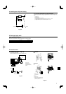
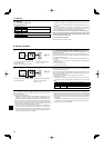
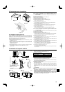
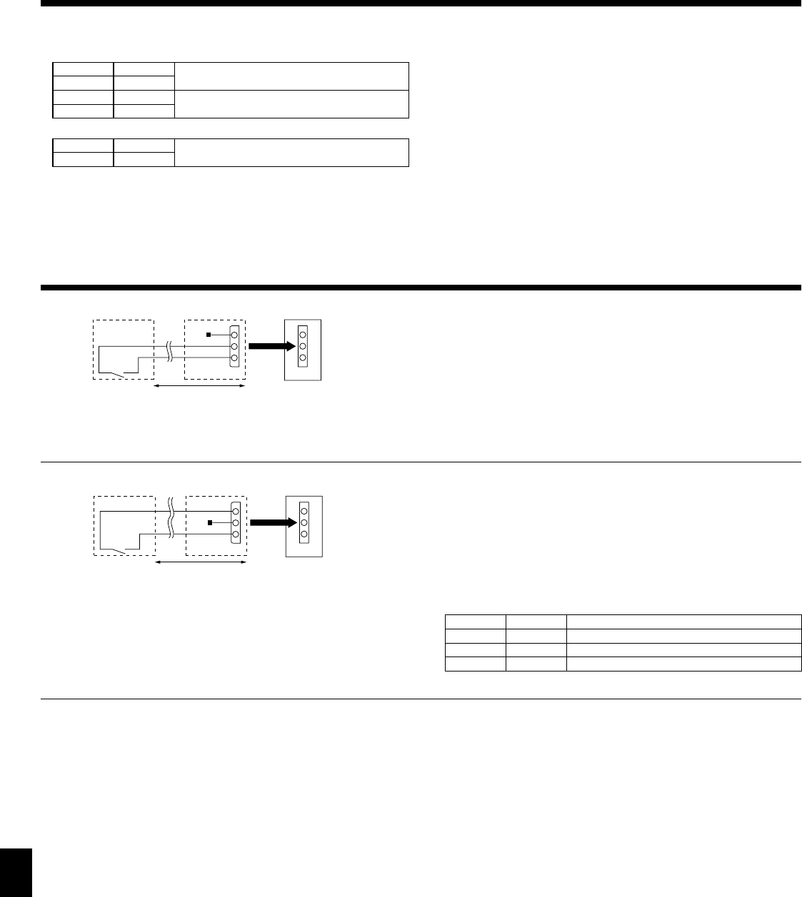
8.1. Low noise mode (on-site modifi cation) (Fig. 8-1)
By performing the following modifi cation, operation noise of the outdoor unit can be
reduced by about 3-4 dB.
The low noise mode will be activated when a commercially available timer or the
contact input of an ON/OFF switch is added to the CNDM connector (option) on the
control board of the outdoor unit.
• The capacity may be insuffi cient according to the outdoor temperature and condi-
tions, etc.
1 Complete the circuit as shown when using the external input adapter (PAC-
SC36NA). (Option)
2 SW1 ON: Low noise mode
SW1 OFF: Normal operation
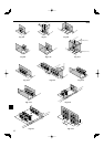
A Circuit diagram example (low noise mode)
B On-site arrangement
C External input adapter (PAC-SC36NA)
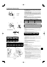
8.3. Refrigerant collecting (pump down)
Perform the following procedures to collect the refrigerant when moving the indoor
unit or the outdoor unit.
1 Supply power (circuit breaker).
* When power is supplied, make sure that “CENTRALLY CONTROLLED” is not
displayed on the remote controller. If “CENTRALLY CONTROLLED” is dis-
played, the refrigerant collecting (pump down) cannot be completed normally.
2 After the gas stop valve is closed, set the SWP switch on the control board of the
outdoor unit to ON. The compressor (outdoor unit) and ventilators (indoor and
outdoor units) start operating and refrigerant collecting operation begins. LED1
and LED2 on the control board of the outdoor unit are lit.
* Only set the SWP switch (push-button type) to ON if the unit is stopped. How-
ever, even if the unit is stopped and the SWP switch is set to ON less than
three minutes after the compressor stops, the refrigerant collecting operation
cannot be performed. Wait until compressor has been stopped for three min-
utes and then set the SWP switch to ON again.
Red
A
B C D
E
SW1
CNDM
3
1
Fig. 8-1
3 Because the unit automatically stops in about two to three minutes after the
refrigerant collecting operation (LED1 and LED2 are lit), be sure to quickly close
the gas stop valve. When LED1 and LED2 are lit and the outdoor unit is stopped,
open the liquid stop valve completely, and then repeat step 2 after three minutes
have passed.
* If the refrigerant collecting operation has been completed normally (LED1 and
LED2 are lit), the unit will remain stopped until the power supply is turned off.
4 Turn off the power supply (circuit breaker).
Brown
Orange
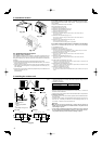
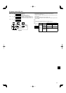
A
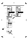
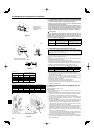
Circuit diagram example (Demand function)
B On-site arrangement
8.2. Demand function (on-site modifi cation) (Fig. 8-2)
By performing the following modifi cation, energy consumption can be reduced to 0
–100% of the normal consumption.
The demand function will be activated when a commercially available timer or the
contact input of an ON/OFF switch is added to the CNDM connector (option) on the
control board of the outdoor unit.
1 Complete the circuit as shown when using the external input adapter
(PAC-SC36NA). (Option)
2 By setting SW7-1 and SW7-2 on the control board of the outdoor unit, the ener-
gy consumption (compared to the normal consumption) can be limited as shown
below.
SW7-1 SW7-2 Energy consumption (SW2 ON)
OFF OFF 0% (Stop)
ON OFF 50%
OFF ON 75%
Red
A
B C D
E
SW2
CNDM
3
1
Brown
Orange
Fig. 8-2
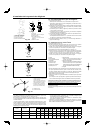
7.2. Test run
7.2.1. Using SW4 in outdoor unit
1) PUH Type, PUZ Type
SW4-1 ON
Cooling operation
SW4-2 OFF
SW4-1 ON
Heating operation
SW4-2 ON
2) PUY Type
SW4-1 ON
Cooling operation
SW4-2 ON or OFF
* After performing the test run, set SW4-1 to OFF.
• After power is supplied, a small clicking noise may be heard from the inside of
the outdoor unit. The electronic expansion valve is opening and closing. The unit
is not faulty.
• A few seconds after the compressor starts, a clanging noise may be heard from
the inside of the outdoor unit. The noise is coming from the check valve due to
the small difference in pressure in the pipes. The unit is not faulty.
The test run operation mode cannot be changed by DIP switch SW4-2 during
the test run. (To change the test run operation mode during the test run, stop
the test run by DIP switch SW4-1. After changing the test run operation mode,
resume the test run by switch SW4-1.)
7.2.2. Using remote controller
Refer to the indoor unit installation manual.
7. Test run
D Outdoor unit control board
E Max. 10 m, 33 ft
C
External input adapter (PAC-SC36NA)
D Outdoor unit control board
E Max. 10 m, 33 ft