


1
(1)
(2)
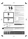
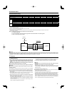
Model
Max height
difference
Additional refrigerant charging amount (kg/oz)
A12, A18 30 m, 100 ft 30 m, 100 ft 0
0.06 kg 0.11 kg 0.17 kg
–––––––
2 oz 4 oz 6 oz
A24, A30, A36 50 m, 165 ft 30 m, 100 ft 0
0.17 kg 0.34 kg 0.51 kg 0.68 kg 0.85 kg 1.02 kg 1.19 kg 1.36 kg 1.53 kg 1.70 kg
6oz 12oz 18oz 24oz 30oz 36oz 42oz 48oz 54oz 60oz
A42 50 m, 165 ft 30 m, 100 ft 0 0 0 0
0.17 kg 0.34 kg 0.51 kg 0.68 kg 0.85 kg 1.02 kg 1.19 kg
6oz 12oz 18oz 24oz 30oz 36oz 42oz
Max pipe
length
20 m 25 m 27 m 30 m 33.5 m 36.6 m 40 m 43 m 45.5 m 48.8 m 50 m
70 ft 80 ft 90 ft 100 ft 110 ft 120 ft 130 ft 140 ft 150 ft 160 ft 165 ft
6
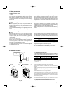
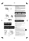
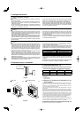
4. Installing the refrigerant piping
4.4. Refrigerant pipe airtight testing method
(1) Connect the testing tools.
• Make sure the stop valves
A
B
are closed and do not open them.
• Add pressure to the refrigerant lines through the service port
C
of the liquid stop valve
D
.
(2) Do not add pressure to the specifi ed pressure all at once; add pressure little by little.
1
Pressurize to 0.5 MPa (5 kgf/cm
2
G), wait 5 minutes, and make sure the pressure does
not decrease.
2
Pressurize to 1.5 MPa (15 kgf/cm
2
G), wait 5 minutes, and make sure the pressure
does not decrease.
3
Pressurize to 4.15 MPa (41.5 kgf/cm
2
G) and measure the surrounding temperature
and refrigerant pressure.
(3) If the specifi ed pressure holds for about one day and does not decrease, the pipes have
passed the test and there are no leaks.
• If the surrounding temperature changes by 1 °C, the pressure will change by about 0.03
MPa (0.3 kgf/cm
2
G). Make the necessary corrections.
(4) If the pressure decreases in steps (2) or (3), there is a gas leak. Look for the source of
the gas leak.
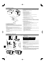
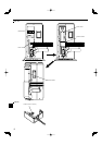
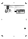
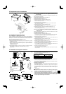
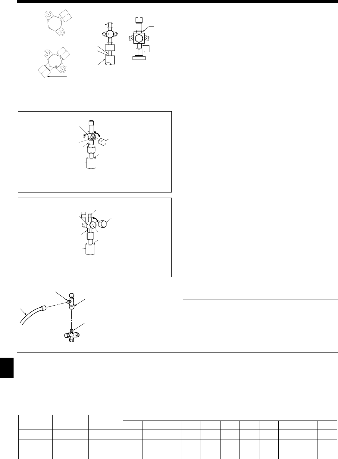
4.5. Stop valve opening method
(1) Gas side of A24-A42 (Fig. 4-5)
1 Remove the cap, pull the handle toward you and rotate 1/4 turn in a counter-
clockwise direction to open.
2 Make sure that the stop valve is open completely, push in the handle and rotate
the cap back to its original position.
(2) Liquid side of A24-A42 and Gas/Liquid side of A12, A18 (Fig. 4-6)
1 Remove the cap and turn the valve rod counterclockwise as far as it will go with
the use of a 4 mm hexagonal wrench. Stop turning when it hits the stopper.
(ø6.35, 1/4 inch: Approximately 4.5 revolutions) (ø9.52, 3/8 inch: Approximately
10 revolutions)
2 Make sure that the stop valve is open completely, push in the handle and rotate
he cap back to its original position.
A Valve
B Unit side
C Operation section
D Cap
E Local pipe side
F Pipe cover
G Service port
H Wrench hole
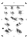
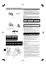
Refrigerant pipes are protectively wrapped for A24-A42
• The pipes can be protectively wrapped up to a diameter of ø90 mm, 3-35/64
inch before or after connecting the pipes. Cut out the knockout in the pipe cover
following the groove and wrap the pipes.
Pipe inlet gap for A24-A42
• Use putty or sealant to seal the pipe inlet around the pipes so that no gaps
remain.(If the gaps are not closed, noise may be emitted or water and dust will
enter the unit and breakdown may result.)
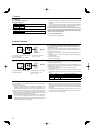
Fig. 4-7
I Double spanner section
(Do not apply a spanner other than to this sec-
tion.Doing so would cause refrigerant leaks.)
J Seal section
(Seal the end of the heat insulation material at
the pipe connection section with whatever seal
material you have on hand so that water does
not infi ltrate the heat insulation material.)
K Handle
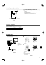
Precautions when using the charge valve (Fig.4-7)
Do not tighten the service port too much when installing it, otherwise, the valve
core could be deformed and become loose, causing a gas leak.
After positioning section B in the desired direction, turn section
A
only and tighten it.
Do not further tighten sections A and B together after tightening section A.
*
The fi gure to the left is an example only.
The stop valve shape, service port po-
sition, etc., may vary according to the
model.
*
Turn section A only.
(Do not further tighten sections A and B
together.)
C Charge hose
D Service port
Stop valve <Liquid side>
Stopvalve <Gas side>
Service port
Open/Close section
Local pipe
Sealed, same way for gas side
Pipe cover
Do not use a wrench here.
Refrigerant leakage may result.
Use 2 wrenches here.
Fig. 4-4
Fig. 4-5
Fig. 4-6
4.6. Addition of refrigerant
• Additional charging is not necessary if the pipe length does not exceed 20 m, 70 ft
for A12-A36, 30 m 100 ft for A42.
•
If the pipe length exceeds the specifi ed length above, charge the unit with addi-
tional R410A refrigerant according to the permitted pipe lengths in the chart below.
* When the unit is stopped, charge the unit with the additional refrigerant through
the liquid stop valve after the pipe extensions and indoor unit have been vacu-
umized.
When the unit is operating, add refrigerant to the gas check valve using a
safety charger. Do not add liquid refrigerant directly to the check valve.
* After charging the unit with refrigerant, note the added refrigerant amount on
the service label (attached to the unit).
Refer to the “1.5. Using R410A refrigerant air conditioners” for more information.
• Be careful when installing multiple units. Connecting to an incorrect indoor unit
can lead to abnormally high pressure and have a serious effect on operation per-
formance.