


21
GB
Remote controller cable length: • 1, 2 10 m (0.3 to 1.25 mm
2
)
If the length exceeds 10 m, use 1.25 mm
2
shielded cable and calculate the length of that portion (L4 and L7) as within the total
extended length and the longest remote length.
11.4. Wiring of main power supply and equipment capacity
Schematic Drawing of Wiring (Example)
[Fig. 11.4.1] (P.10)
A
Switch (Breakers for wiring and current leakage)
B
Breakers for current leakage
C
Outdoor unit
D
Pull box
E
Indoor unit
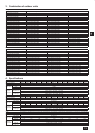
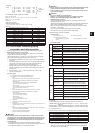
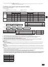
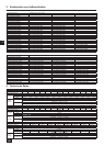
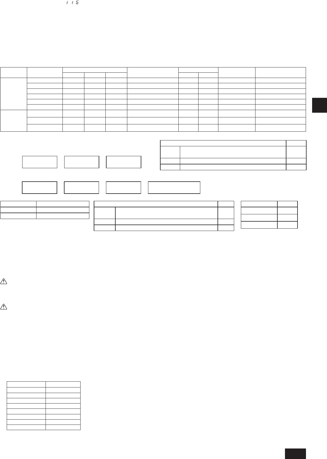
Thickness of wire for main power supply, capacities of the switch and system impedance
Model
Minimum wire thickness (mm
2
)
Breaker for current leakage
Local swtich(A)
Breaker for wiring
(NFB) (A)
Max. Pemissive
System Impedance
Main cable Branch Ground
Capacity Fuse
Outdoor unit
PUHY-(E)P200YJM
4.0 - 4.0
30A 100mA 0.1sec. or less
25 25 30 *1
PUHY-(E)P250YJM
4.0 - 4.0
30A 100mA 0.1sec. or less
32 32 30 *1
PUHY-(E)P300YJM
4.0 - 4.0
30A 100mA 0.1sec. or less
32 32 30 *1
PUHY-P350YJM
6.0 - 6.0
40A 100mA 0.1sec. or less
40 40 40 0.27 Ω
PUHY-P400YJM
10.0 - 10.0
60A 100mA 0.1sec. or less
63 63 60 0.22 Ω
PUHY-P450YJM
10.0 - 10.0
60A 100mA 0.1sec. or less
63 63 60 0.19 Ω
Total
operatng
current of the
indoor unit
F0=20A or less*2
1.5 1.5 1.5
20 A current sensitivity *3
20 20 20 (apply to IEC 61000-3-3)
F0=30A or less*2
2.5 2.5 2.5
30 A current sensitivity *3
30 30 30 (apply to IEC 61000-3-3)
F0=40A or less*2
4.0 4.0 4.0
40 A current sensitivity *3
40 40 40 (apply to IEC 61000-3-3)
*1: Meets technical requirements of IEC61000-3-3
1. Use dedicated power supplies for the outdoor unit and indoor unit. Ensure OC and OS are wired individually.
2. Bear in mind ambient conditions (ambient temperature, direct sunlight, rain water, etc.) when proceeding with the wiring and connections.
3. The wire size is the minimum value for metal conduit wiring. If the voltage drops, use a wire that is one rank thicker in diameter.
Make sure the power-supply voltage does not drop more than 10%.
4. Specic wiring requirements should adhere to the wiring regulations of the region.
5. Power supply cords of parts of appliances for outdoor use shall not be lighter than polychloroprene sheathed exible cord (design 245 IEC57).
6. A switch with at least 3 mm contact separation in each pole shall be provided by the Air Conditioner installer.
Warning:
Be sure to use specied wires for connections and ensure no external force is imparted to terminal connections. If connections are not xed rmly, •
heating or re may result.
Be sure to use the appropriate type of overcurrent protection switch. Note that generated overcurrent may include some amount of direct current.•
Caution:
Some installation sites may require attachment of an earth leakage breaker for the inverter. If no earth leakage breaker is installed, there is a danger of •
electric shock.
Do not use anything other than a breaker and fuse with the correct capacity. Using a fuse or wire of too large capacity may cause malfunction or re.•
Note:
This device is intended for the connection to a power supply system with a maximum permissible system impedance shown in the above table at the •
interface point (power service box) of the user’s supply.
The user must ensure that this device is connected only to a power supply system which fulls the requirement above. •
If necessary, the user can ask the public power supply company for the system impedance at the interface point.
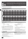
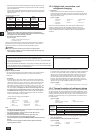
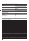
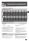
This equipment complies with IEC 61000-3-12 provided that the short-circuit power Ssc is greater than or equal to Ssc (*2) at the interface point between •
the user’s supply and the public system. It is the responsibility of the installer or user of the equipment to ensure, by consultation with the distribution
network operator if necessary, that the equipment is connected only to a supply with a short-circuit power Ssc greater than or equal to Ssc (*2).
S
SC
(*2)
Model S
SC
(MVA)
PUHY-(E)P200YJM
1.24
PUHY-P250YJM
1.41
PUHY-EP250YJM
1.27
PUHY-P300YJM
1.70
PUHY-EP300YJM
1.51
PUHY-P350YJM
2.08
PUHY-P400YJM
2.48
PUHY-P450YJM
2.92
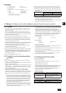
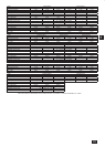
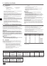
Indoor unit V2
Type 1
PLFY-VBM, PMFY-VBM, PEFY-VMS, PCFY-VKM,
PKFY-VHM, PKFY-VKM, PFFY-VKM, PFFY-VLRMM
2.4
Type 2 PEFY-VMA 1.6
Others Other indoor unit 0
Wire thickness V3
1.5 mm
2
48
2.5 mm
2
56
4.0 mm
2
66
G1 Current sensitivity
30mA or less 30mA 0.1sec or less
100mA or less 100mA 0.1sec or less
*2: Please take the larger of F1 or F2 as the value for F0.
F1 = Total operating maximum current of the indoor units x 1.2
F2 =
*3: Current sensitivity is calculated using the following formula.
G1 =
V1 x Quantity
of Type A
+
V1 x Quantity
of Type B
+
V1 x Quantity
of Others
V2 x Quantity
of Type 1
+
V2 x Quantity
of Type 2
+
V2 x Quantity
of Others
+
V3 x Wire length [km]
Indoor unit V1
Type A
PLFY-VBM, PMFY-VBM, PEFY-VMS, PCFY-VKM,
PKFY-VHM, PKFY-VKM, PFFY-VKM, PFFY-VLRMM
1.6
Type B PEFY-VMA 3.2
Others Other indoor unit 0
2 Wiring examples
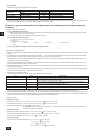
Controller name, symbol and allowable number of controllers.•
Name Code Possible unit connections
Outdoor unit
Main unit OC – (*2)
Sub unit OS1, OS2 – (*2)
Indoor unit Indoor unit controller IC 1 to 32 units per 1 OC (*1)
Remote controller Remote controller (*1) RC 2 units maximum per group
Other Transmission booster unit RP 0 to 1 unit per 1 OC (*1)
*1 A transmission booster (RP) may be required depending on the number of connected indoor unit controllers.
*2 OC, OS1, and OS2 of the outdoor units in the same refrigerant system are automatically identied. They are identied as OC, OS1, and OS2 in descending order of
capacity. (If the capacity is the same, they will be in ascending order of their address number.)
Example of a group operation system with multiple outdoor units (Shielding wires and address setting are
necessary.)
<Examples of transmission cable wiring>
[Fig. 11.3.1] ME Remote Controller (P.9)
*1: When the power supply unit is not connected to the transmission line for centralized control, disconnect the male power supply connector (CN41) from ONE
outdoor unit in the system and connect it to CN40.
*2: If a system controller is used, set SW2-1 on all of the outdoor units to ON.
[Fig. 11.3.2] MA Remote Controller (P.10)
<A> Change the jumper connector from CN41 to CN40
<B> SW2-1:ON
<C> Keep the jumper connector on CN41
A
Group 1
B
Group 3
C
Group 5
D
Shielded wire
E
Sub remote controller
( ) Address
[Fig. 11.3.3] Combination of outdoor units and transmission booster unit (P.10)
<Wiring Method and Address Settings>
a. Always use shielded wire when making connections between the outdoor unit (OC) and the indoor unit (IC), as well for all OC-OC, OC-OS, OS-OS, and IC-IC wiring
intervals.
b. Use feed wiring to connect terminals M1 and M2 and the earth terminal
on the transmission line terminal block (TB3) of each outdoor unit (OC) to terminals M1,
M2 and terminal S on the transmission line block of the indoor unit (IC). For OC and OS, connect TB3 to TB3.
c. Connect terminals 1 (M1) and 2 (M2) on the transmission line terminal block of the indoor unit (IC) that has the most recent address within the same group to the
terminal block on the remote controller (RC).
d. Connect together terminals M1, M2 and terminal S on the terminal block for central control (TB7) for the outdoor unit in a different refrigerant system (OC). For OC
and OS in the same refrigerant system, connect TB7 to TB7.
e. When the power supply unit is not installed on the central control transmission line, change the jumper connector on the control board from CN41 to CN40 on only
one outdoor unit in the system.
f. Connect the terminal S on the terminal block for central control (TB7) for the outdoor unit (OC) for the unit into which the jumper connector was inserted into CN40 in
the step above to the earth terminal
in the electrical component box.
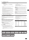
g. Set the address setting switch as follows.
* To set the outdoor unit address to 100, the outdoor address setting switch must be set to 50.
Unit Range Setting Method
Indoor unit (Main) 01 to 50 Use the most recent address within the same group of indoor units.
Indoor unit (Sub) 01 to 50
Use an address, other than that of the IC (Main) from among the units within the same group of indoor
units. This must be in sequence with the IC (Main).
Outdoor Unit (OC, OS) 51 to 100
Set the addresses of the outdoor units in the same refrigerant system in the order of sequential
number. OC, OS1, and OS2 are automatically identied. (*1)
ME R/C (Main) 101 to 150 Set at an IC (Main) address within the same group plus 100.
ME R/C (Sub) 151 to 200 Set at an IC (Main) address within the same group plus 150.
MA R/C – Unnecessary address setting (Necessary main/sub setting)
h. The group setting operations among the multiple indoor units is done by the remote controller (RC) after the electrical power has been turned on.
i. When the centralized remote controller is connected to the system, set centralized control switches (SW2-1) on control boards in all outdoor units (OC, OS) to “ON”.
*1 OC, OS1, and OS2 of the outdoor units in the same refrigerant system are automatically identied. They are identied as OC, OS1, and OS2 in descending order of
capacity (If the capacity is the same, they are identied in the ascending order of their address number).
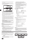
<Permissible Lengths>
1 ME Remote controller
Max length via outdoor units: L•
1+L2+L3+L4 and L1+L2+L3+L5 and L1+L2+L6 500 m (1.25 mm
2
or more)
Max transmission cable length: L•
1 and L3+L4 and L3+L5 and L6 and L2+L6 200 m (1.25 mm
2
or more)
Remote controller cable length: •
1, 2, 3, 4 10 m (0.3 to 1.25 mm
2
)
If the length exceeds 10 m, use a 1.25 mm
2
shielded wire. The length of this section (L8) should be included in the calculation of
the maximum length and overall length.
2 MA Remote controller
Max length via outdoor unit (M-NET cable): L•
1+L2+L3+L4 and L1+L2+L6 500 m (1.25 mm
2
or more)
Max transmission cable length (M-NET cable): L•
1 and L3+L4 and L6 and L2+L6 200 m (1.25 mm
2
or more)
Remote controller cable length: • m
1+m2 and m1+m2+m3+m4 200 m (0.3 to 1.25 mm
2
)
3 Transmission booster
Max transmission cable length (M-NET cable): • 1 L
1+L2+L3+L5+L6 200 m (1.25 mm
2
)
2 L
1+L2+L3+L5+L7 200 m (1.25 mm
2
)
3 L
1+L2+L4 200 m (1.25 mm
2
)
4 L
6+L5+L3+L4, L4+L3+L5+L7 200 m (1.25 mm
2
)
WT05962X01_GB.indd 21 2010/08/26 19:21:00