


70
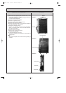
OPERATING PROCEDURE PHOTOS
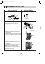
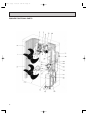
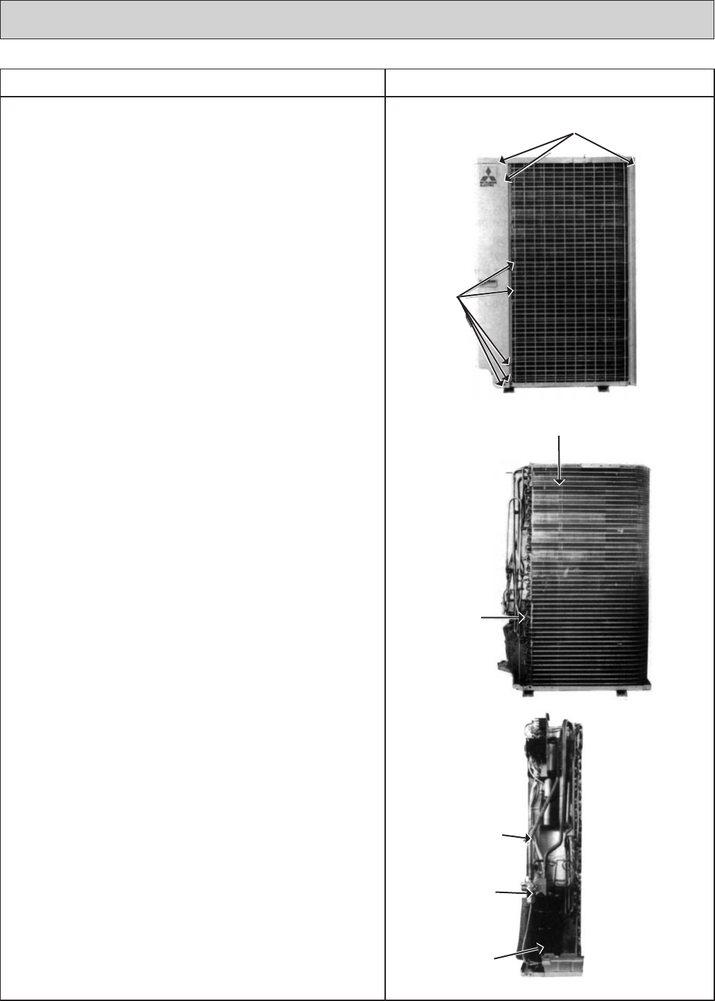
3. Heat Exchanger, Compressor
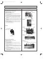
(1) Remove the rear / right side panel (2 screws in front, 1 screw
on the side, 3 screws in the rear).
Remove the electrical box, valve bed, and open to the rear
to remove (anchors attached).
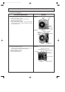
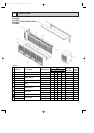
(2) Remove right side panel (4 screws).
(3) Remove rear guard (3 screws).
(4) Remove separator support plate (4 screws).
(5) Remove motor support (2 screws).
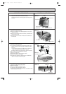
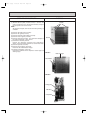
(6) Remove valve bed (5 screws). The valve bed is clasped on
the right and left sides. Lift to remove.
(7) Remove the electrical parts box.
Remove the respective connectors from highpressure
switch, Low-pressure switch, crank case heater, shell ther-
mo, and fan motor lead.
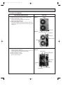
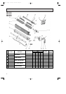
(8) Remove separator (2 screws).
(9) Remove heat exchanger (2 screws).
Remove piping weld zone.
(10) Remove compressor (3 set nuts).
Remove the weldment of the compressor suction pipe and
discharge pipe.
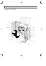
NOTE :
All panels are clasped, and must be removed by shifting up
and down.
Screws
Screws
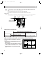
Photo 4
Heat exchanger
Accumulator
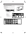
Photo 5
Charge plug
Ball valve
Compressor
Photo 6
OC120--3.qxp 24/6/97 12:58 AM Page 70