


60
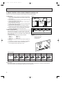
2. GROUP CONTROL WITH A SINGLE REMOTE CONTROLLER
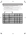
A maximum of 50 units can be started in order according to the dip switch settings
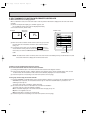
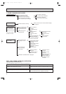
2-1 How to wire
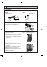
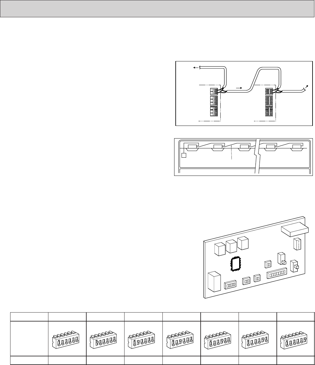
(1) Connect the remote controller to the double terminal block
on the indoor controller board of the master unit (No.0 unit).
(See Figure 1.)
(2) Connect the double terminal block of the master unit to the
double terminal block of No.1 unit.
(3) Connect the double terminal block of No.1 unit to the dou-
ble terminal block of No.2 unit.
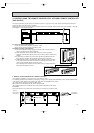
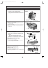
(4) Continue the process until all the units are connected with
two-wire cables. (See Figure 2.)
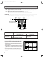
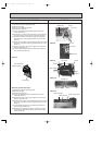
(5) Remove the connector CN40 from the indoor controller
board of each unit except the master unit. (See Figure 3.)
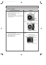
(6) Set the unit-address of each unit with SW2 on the indoor
controller board following the instructions below.
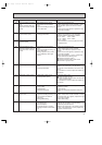
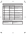
2-2 How to set unit-address
The unit-address also serves as a successive-start timer which
starts each unit at intervals of 1 second. If two or more units
have the same unit-address in a group control, operation stops
due to system error. Be sure to set SW2 correctly following the
instructions below.
(1) Each lever of SW2 shows the number as follows.
SW2-1 : 1 SW2-4 : 8
SW2-2 : 2 SW2-5 : 16
SW2-3 : 4 SW2-6 : 32
(2) Total number of levers turned to ON shows the address of
the unit.
For example, to set No.3 unit, turn ON SW2-1 and SW2-2.
(3) In this way, set from the. master unit to the last unit.
Do not forget to set the master (No. 0) unit.
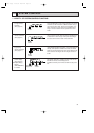
2-3 Unit control
The remote controller can control all units ON/OFF, temperature,air flow, and swing louver. However, the thermostat in
each unit turns ON or OFF individually to adjust to the room temperature.
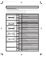
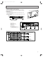
Unit address & start
delay in seconds.
SW2
Master (No. 0) unit
0
1
2
3
4
5
6
ALL OFF
No. 1 unit
1
1
2
3
4
5
6
1 ON
No. 2 unit
2
1
2
3
4
5
6
2 ON
No. 4 unit
4
1
2
3
4
5
6
3 ON
No. 8 unit
8
1
2
3
4
5
6
4 ON
No. 16 unit
16
1
2
3
4
5
6
5 ON
No. 32 unit
32
1
2
3
4
5
6
6 ON
Setting examples
To remote
controller
To next
unit
To next unit
The last unit
dose not have
this wire.
Next unit
electrical box
Master unit
electrical box
123ANE
123ANE
Master
unit
No.1 unit No.2 unit Last unit
2-wire cable
Figure 2
Figure 3
Indoor controller board CN40
Should be removed from
all units other than unit
No.0:(Master Unit)
Figure 1
OC120--2.qxp 24/6/97 12:33 AM Page 60