


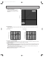
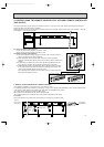
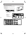
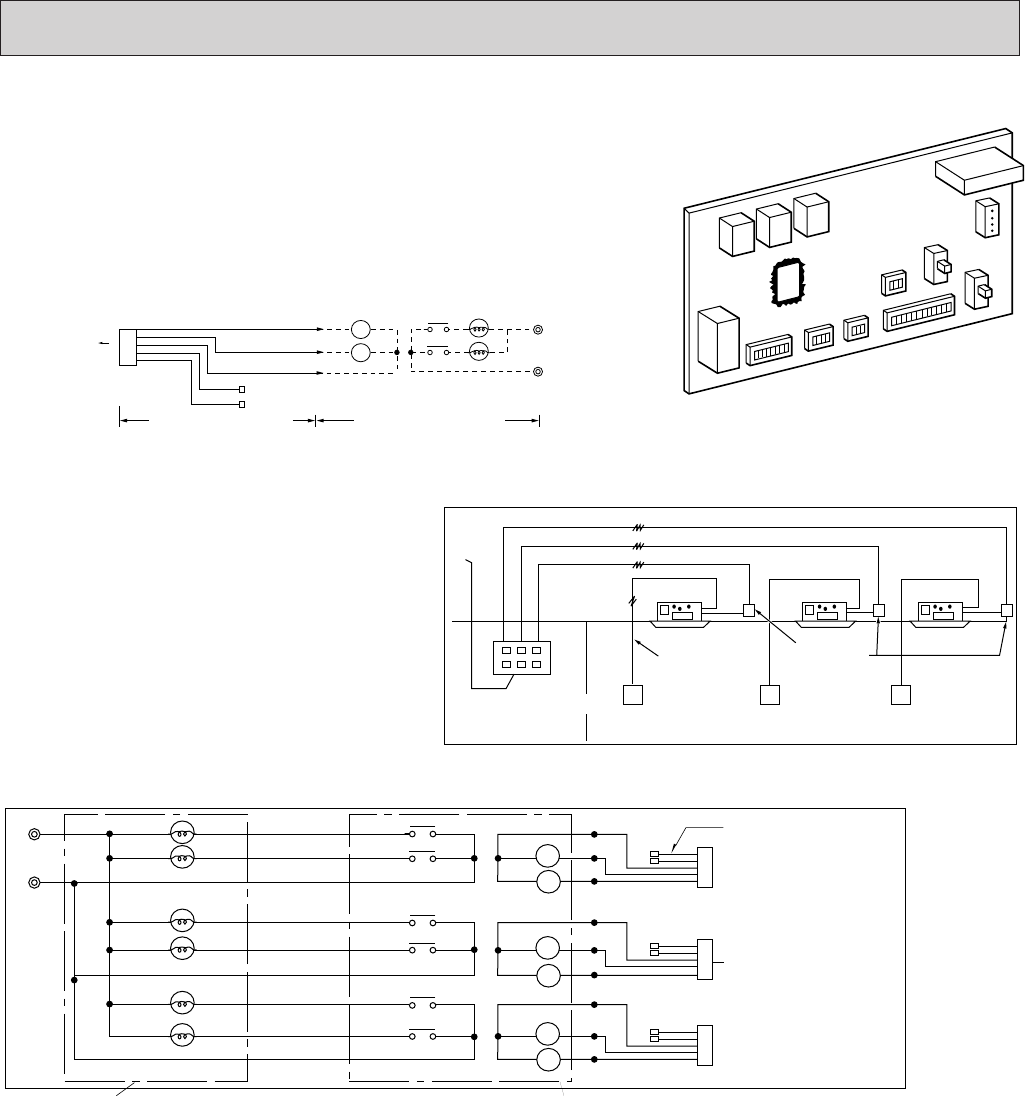
6. MULTIPLE REMOTE CONTROL DISPLAY
You can control serveral units with a multiple remote control display,by
wiring an optional multipe display adapter (PAC-SA88HA-E) with relays
and lamps on the market.
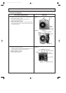
6-1 How to wire
(1) Connect the multipe display adapter to the connector CN51 on the
indoor controller board.
(2) Wire three of the five wires from the multiple display adapter as shown
in the figure below.
[Notes on Signs]
X1:Relay (for check lamp)
X2:Relay (for operation lamp)
RL:Check Lamp
GL:Operation Lamp
[Field supplied parts]
Relays:12V DC with rated coil power con-
sumption below 0.9W.
Lamps:Matching to power supply voltage.
CN51
connector(5P)
GREEN
Power
supply
Electrical insulation is needed.
Wiring at the actual place
Optional multiple display
adapter
The maximumdistance between
indoor board and relay is 10m.
YELLOW
ORANGE
RED
BROWN
5
X1
X1
RL
GL
X2
X2
1
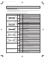
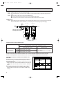
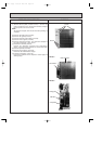
<Wiring >
Power
supply
Remote
controller
cable
Relay box
(Field supply)
Remote
controller
Remote
controller
Remote
controller
3wires
3wires
3wires
2wires
No.1 unit No.2 unit No.3 unit
Muitiple remote control
ON-OFF display
(Field supply)
(Operation check)
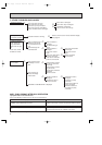
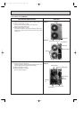
<System>
Power
supply
RL-1
GL-1
Multiple Remote Control Display
Multiple remote
controller adapter
connect to
the connector CN51
Relay box
5
X1-1
X2-1
1
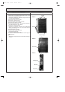
<Wiring diagram>
RL-2
GL-2
RL-3
No.1 unit
GL-3
X1
X2
5
1
No.2 unit
X1
X2
5
1
No.3 unit
X1
X2
X1-2
X2-2
X1-3
X2-3
Indoor controller board
63
OC120--2.qxp 24/6/97 12:33 AM Page 63