58
OPERATING PROCEDURE
PHOTOS
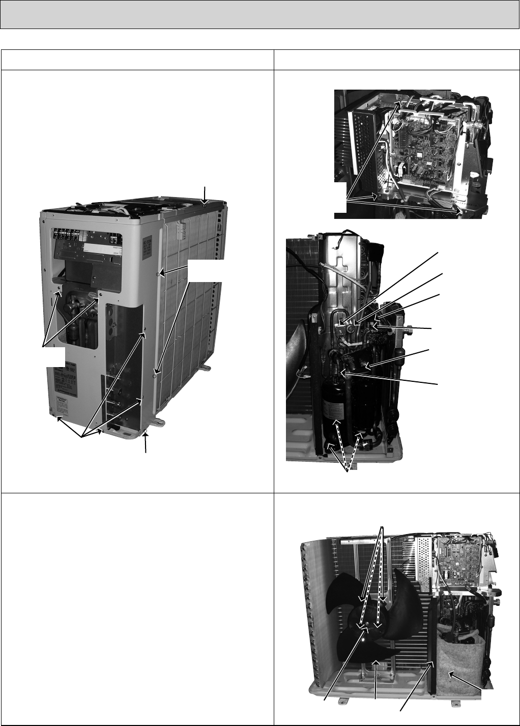
3. Removing the fan motor
(1) Remove the top panel, the service panel, and the cabinet
(Photo 1, 2).
(2) Disconnect the connector CN931 and CN932 on the outdoor
electronic control P.C. board.
(3) Remove the propeller.
(4) Remove the fan motor.
Photo 4
2. Removing the electronic control P.C. board
(1) Remove the screws of the sub panel.
(2) Remove the sub panel.
(3) Disconnect all connectors and lead wires on the electronic
control P.C. board.
(4) Remove the electronic control P.C. board.
Photo 3
Screw of the rear guard
Screws of the
back panel
Screw of the
back panel
Screws of
the back panel
Screws of
the back panel
Screws of
the electrical
parts
R.V. coil
4 way valve
LEV coil E
Expansion valve E
Suction pipe
welded part
Discharge
pipe welded part
Photo 5
Compressor nuts
Photo 6
Screws of the outdoor fan motor
Propeller
Propeller nut
Separator
Sound
proof
felt


