


41
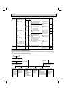
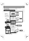
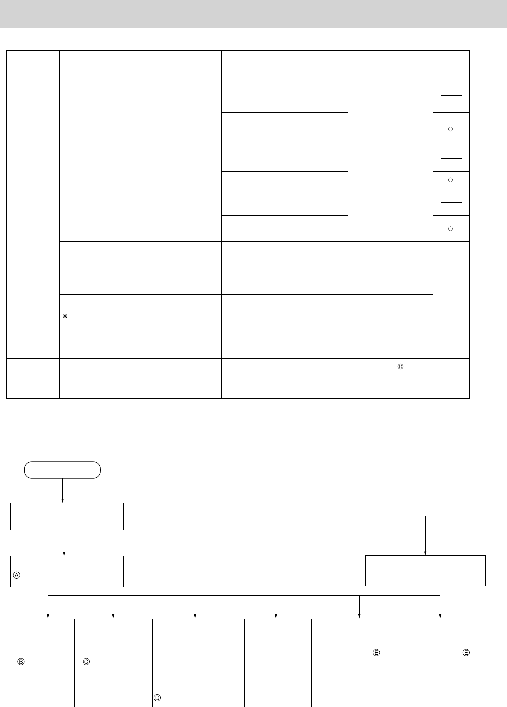
Operation start
Check the outdoor unit
LED indicator.
Refer to 11-6.
"Check of power supply".
• Indoor unit
serial signal
error
Refer to 11-6.
"How to
check
mis-wiring and
serial signal
error".
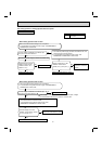
• COOL or
HEAT
operation only
Refer to 11-6.
"Check of
R.V. coil".
• When cooling,
room is not
cool.
Refer to 11-6.
"How to check
inverter/
compressor".
• When cooling, heat
exchanger of
non-operating indoor
unit frosts.
•When heating, non-
operating indoor unit
gets warm.
Refer to 11-6.
"Check of LEV".
• When heating,
room does not get
warm.
Refer to 11-6.
"How to check
inverter/compressor".
Check mis-piping,
shortage of capacity.
• When cooling
dew drops in the
non-operating
indoor unit.
Check of
miss-piping.
Refer to 11-4.
"Troubleshooting check table".
Both LED1 and
LED2 are OFF.
Both LED 1 and
LED 2 are lighting.
LED 1 or LED 2
has blinked.
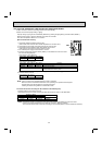
11-3. INSTRUCTION OF TROUBLESHOOTING
• Check the indoor unit with referring to the indoor unit service manual, and confirm that there is any problem in the indoor
unit.
Then, check the outdoor unit with referring to this page.
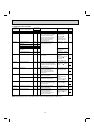
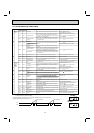
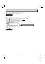
11-time flash
15-time flash
• Check the connecting
wire between outdoor
electronic control
P.C. board and power
board.
• Replace the power
board.
• Check the connecting
wire among electronic
control P.C. board,
noise filter P.C. board
and power board.
• Check the voltage of power
supply.
• Replace the power board.
• Check the voltage of power
supply.
• Replace the outdoor
electronic control P.C. board.
• Refer to 11-6. "Check
of LEV".
• Check the drain pump of
the indoor unit.
When the communication between
boards protection stop is
continuously performed twice.
Communication error occurs
between the electronic control P.C.
board and power board for more
than 10 seconds.
Current sensor protection stop is
continuously performed twice.
When a short or open circuit is
detected in the current sensor
during compressor operating.
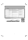
The protection stop of the zero
cross detecting circuit is
continuously performed 10 times.
When zero cross signal cannot be
detected while the compressor is
operating.
When a failure is detected in the
operation of the converter during
operation.
When the bus-bar voltage exceeds
400V or falls to 200V or below
during compressor operating.
When the bus-bar voltage exceeds
400V or falls to 50V or below during
compressor operating.
Communication error
between P.C. boards
Current sensor
Zero cross detecting circuit
Converter
Bus-bar voltage
(1)
Bus-bar voltage
(2)
Even if this protection stop is
performed continuously three
times, it does not mean the
abnormality in outdoor power
system.
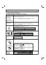
LEV for drain
Lighting 6 times
Lighting 7 times
5 times Goes
out
5 times
Goes
out
5 times
6 times
Goes
out
Goes
out
When the indoor unit detects any
abnormal in the LEV for drain.
Lighting
Lighting
Abnormal point
(Failure mode/protection)
Condition
Remedy
Indoor/outdoor
unit failure mode
recall function
LED indication
(Outdoor P.C. board)
LED1 LED2
The left lamp of
OPERATION INDICATOR
lamp(Indoor unit)
NOTE: Blinking patterns of this mode differ from the ones of Troubleshooting check table (11-4.).