


47
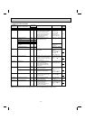
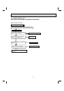
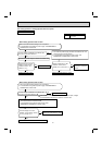
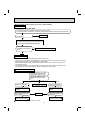
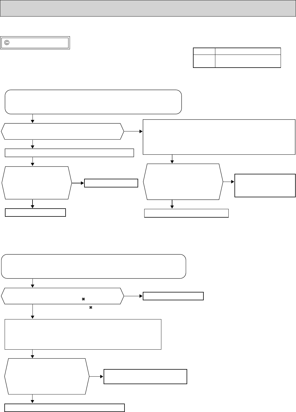
Check of R.V. coil
No
Yes
No
Yes
No
Yes
No
Yes
No
Yes
1. Disconnect the lead wire leading to the compressor.
2. 3 minutes after turning ON the power supply, start EMERGENCY
OPERATION in HEAT mode.
Is there voltage of 208/230 V AC between pin1
and pin 2 at connector CN912 ?
Turn OFF the power supply of indoor and outdoor unit.
1. Turn OFF the power supply of indoor and outdoor unit, and
disconnect the connector CN781.
2. 3 minutes after turning ON the power supply, start
EMERGENCY OPERATION in HEAT mode.
Replace the 4-way valve.
Replace the noise filter P.C. board.
Replace the R.V. coil.
Is there voltage of 12 V DC
between the connector
CN781 pin 5 (+) and pin 3 (-) ?
Replace the outdoor
electronic control P.C.
board.
Disconnect the connector
CN912. Is there normal
resistance to R.V. coil ?
(Refer to 11-5.)
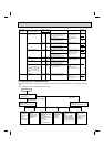
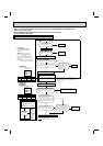
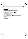
1. Disconnect the lead wire leading to the compressor.
2. 3 minutes after turning ON the power supply, start EMERGENCY
OPERATION in COOL mode.
Is there voltage of 208/230 V AC between pin1
and pin 2 at connector CN912 ?
1. Turn OFF the power supply of the indoor and the outdoor unit,
and disconnect the connector CN781.
2. 3 minutes after turning ON the power supply, start
EMERGENCY OPERATION in COOL mode.
Replace the 4-way valve.
Replace the noise filter P.C. board.
Is there voltage of 12 V DC
between the connector CN781
pin 5 (+) and pin 3 (-) ?
Replace the outdoor electronic control P.C. board.
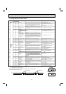
If the connector CN912 is not connected or R.V. coil is open, voltage
occurs between terminals even when the control is OFF.
• When heating operation does not work.
• When cooling operation does not work.
The cooling operation or heating operation does not operate.
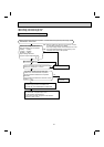
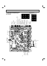
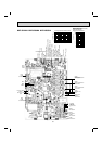
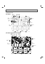
CN912
CN781
Noise filter P.C. board
Outdoor electronic control
P.C. board