


24
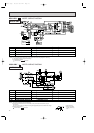
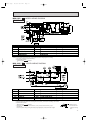
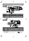
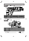
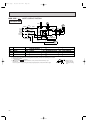
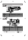
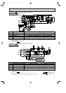
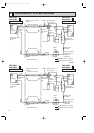
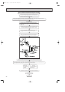
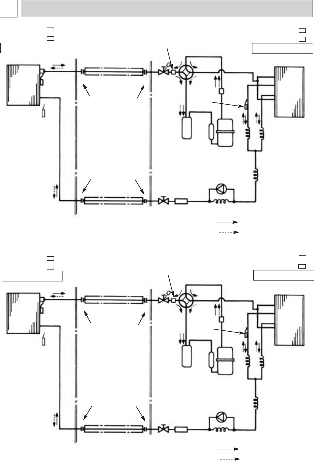
REFRIGERANT SYSTEM DIAGRAM
6
MSH-07NV -
MSH-07NV -
E2
E1
MUH-07NV -
MUH-07NV -
E2
E1
INDOOR UNIT
OUTDOOR UNIT
Indoor
heat
exchanger
Room temperature
thermistor
RT11
(with heat insulator)
Flared connection
Flared connection
Refrigerant pipe [ 9.52
(Option)
Muffler
Reversing valve
(4-way valve)
Defrost
thermistor
RT61
Accumulator
Strainer
Outdoor
heat
exchanger
Capillary tube
[1.4x800 (2 pcs)
Capillary tube
[1.6x750
Capillary tube
[1.4x850
Check
valve
Strainer
Refrigerant pipe [6.35 Stop valve
(Option)
(with heat insulator)
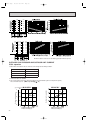
Refrigerant flow in cooling
Refrigerant flow in heating
Unit:mm
Unit:mm
Stop valve
(with service
port)
Indoor coil
thermistor
RT12
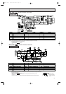
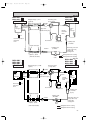
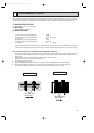
MSH-09NV -
MSH-09NV -
E2
E1
MUH-09NV -
MSH-09NV -
E2
E1
INDOOR UNIT
OUTDOOR UNIT
Indoor
heat
exchanger
Room temperature
thermistor
RT11
(with heat insulator)
Flared connection
Flared connection
Refrigerant pipe [9.52
(Option)
Muffler
Reversing valve
(4-way valve)
Defrost
thermistor
RT61
Accumulator
Strainer
Outdoor
heat
exchanger
Capillary tube
[1.4x800 (2 pcs)
Capillary tube
[1.6x400
Capillary tube
[1.6x1300
Check
valve
Strainer
Refrigerant pipe [6.35 Stop valve
(Option)
(with heat insulator)
Reversing valve coil
(4-way valve coil)
heating ON
cooling OFF
Refrigerant flow in cooling
Refrigerant flow in heating
Stop valve
(with service
port)
Indoor coil
thermistor
RT12
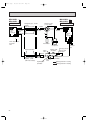
Reversing valve coil
(4-way valve coil)
heating ON
cooling OFF
OB207t-1qxp 25/9/97 8:53 PM Page 24