


20
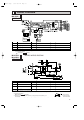
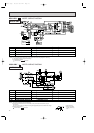
MUH-12NV -
E2
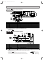
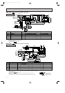
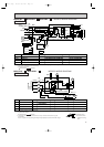
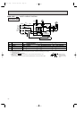
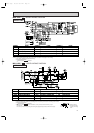
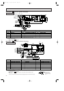
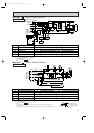
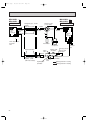
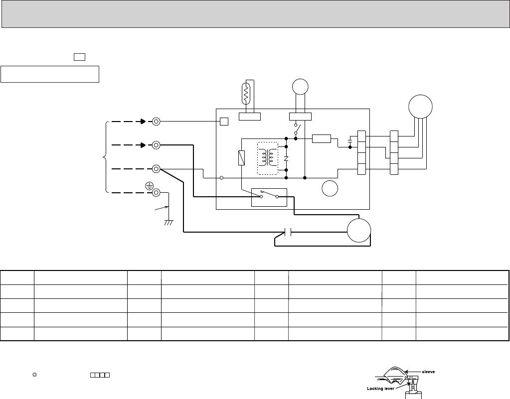
MODEL WIRING DIAGRAM
OUTDOOR UNIT
21S4
SR61
CN661 CN721
X62
MC
MF
52C
4
3
WHT
RED
BLU
BLU
BLK
WHT
ORN
RED
BLK
WHT
RED
TRANS
R
S
C
C1
RED
BLK
12VDC
GRN/YLW
TO
INDOOR UNIT
CONNECTING
TB
220-240V~2
N
2
3
4
1
4
3
2
1
RT61
CN730
F61
BLK
BLK
X62
C65
TAB20
NR61
CN711
DEICER P.C.BOARD
1
WHT
IC881
3
❈
❈
❈
❈
❈
❈
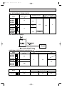
SYMBOL
X62
21S4
52C
SYMBOL
MF
NR61
RT61
SYMBOL
C1
F61
MC
SR61
NAME
NAME NAME
COMPRESSOR CAPACITOR
FUSE(2A)
COMPRESSOR<INNER THERMOSTAT>
SOLID STATE RELAY
OUTDOOR FAN MOTOR
VARISTOR
DEFROST THERMISTOR
REVERSING VALVE COIL RELAY
REVERSING VALVE COIL
CONTACTOR
SYMBOL
C65
IC881
TB
NAME
FAN MOTOR CAPACITOR
DC/DC CONVERTER
TERMINAL BLOCK
<INNER THERMOSTAT>
NOTE:1. Use copper conductors only.(For field wiring)
2. Since the indoor and outdoor unit connecting wires have polarity, connect them according to the numbers.
3. Symbols below indicate.
: Terminal block, : Connector
4. “❈”show the terminals with a lock mechanism, so they cannot be removed when you pull
the lead wire.
Be sure to pull the wire by pushing the locking lever(projected part) of the terminal with a finger.
1.Slide the sleeve.
2.Pull the wire while
pushing the locking
lever.
OB207t-1qxp 25/9/97 8:52 PM Page 20