


16
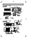
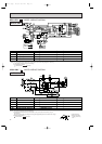
MSH-12NV -
E1
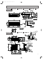
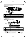
MUH-12NV -
E1
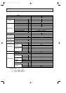
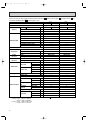
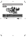
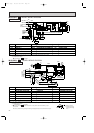
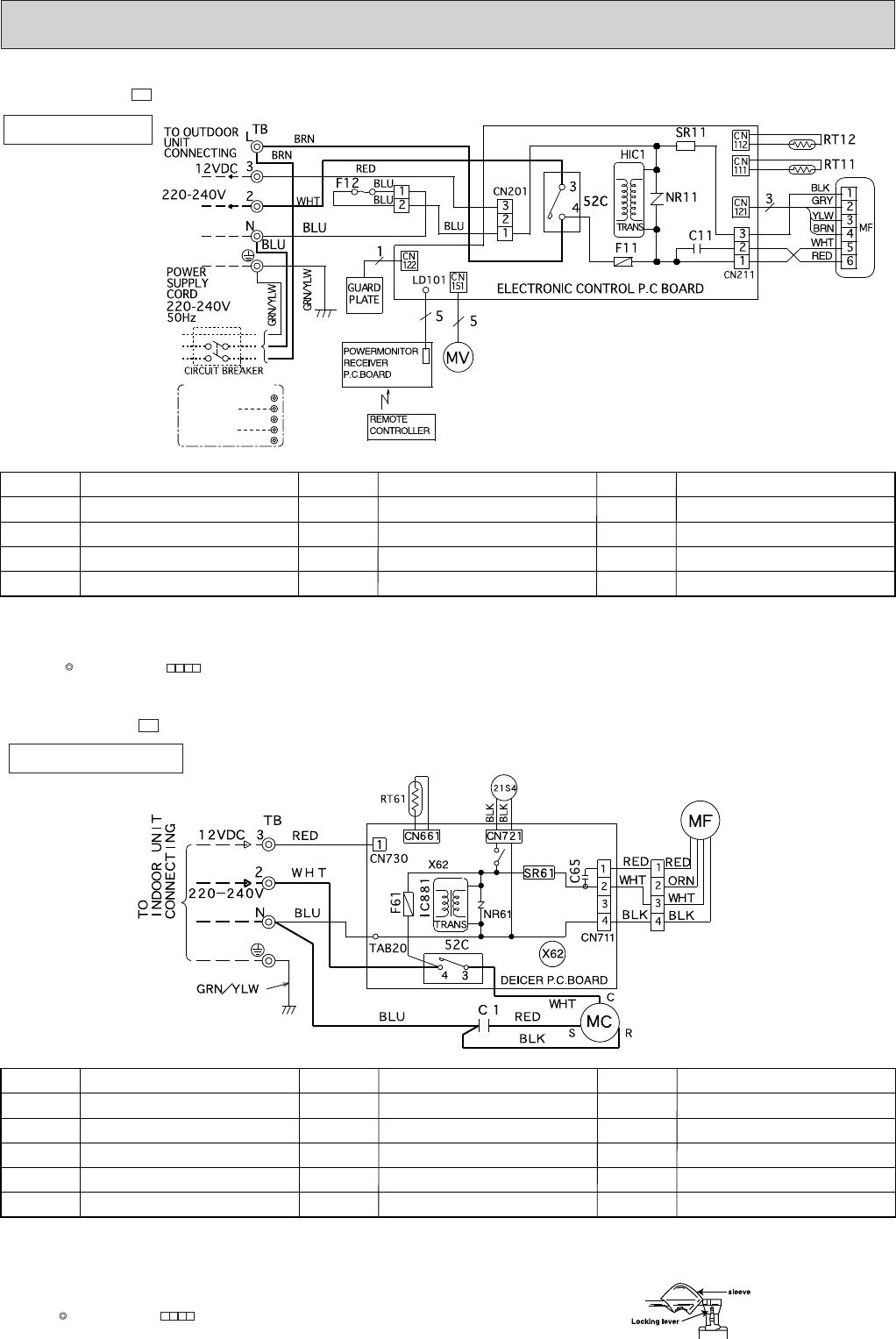
MODEL WIRING DIAGRAM
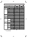
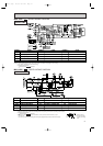
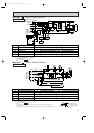
MODEL WIRING DIAGRAM
INDOOR UNIT
OUTDOOR UNIT
❈
❈
❈
❈
❈
❈
~/N
~
TO OUTDOOR
UNIT
CONNECTING
12VDC
L
3
2
N
;
FOR MULTI SYSTEM
SYMBOL
TB
MV
SR11
SYMBOL
NR11
RT11
RT12
52C
SYMBOL
C11
F12
F11
MF
NAME
NAME NAME
INDOOR FAN CAPACITOR
FUSE(93:)
FUSE(3.15A)
INDOOR FAN MOTOR
VARISTOR
ROOM TEMPERATURE THERMISTOR
INDOOR COIL THERMISTOR
CONTACTOR
TERMINAL BLOCK
VANE MOTOR
SOLID STATE RELAY
❈
❈
❈
❈
❈ ❈
SYMBOL
X62
21S4
IC881
SYMBOL
MF
NR61
RT61
SR61
TB
SYMBOL
C1
C65
52C
F61
MC
NAME
NAME NAME
COMPRESSOR CAPACITOR
OUTDOOR FAN MOTOR CAPACITOR
CONTACTOR
FUSE(2A)
COMPRESSOR(INNER THERMOSTAT)
OUTDOOR FAN MOTOR
VARISTOR
DEFROST THERMISTOR
SOLID STATE RELAY
TERMINAL BLOCK
REVERSING VALVE COIL RELAY
REVERSING VALVE COIL
DC/DC CONVERTER
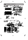
NOTE:1. For the outdoor electric wiring refer to the outdoor unit electric wiring diagram for servicing.
2. Use copper conductors only.(For field wiring)
3. Symbols below indicate.
: Terminal block, : Connector
NOTE:1. Use copper conductors only.(For field wiring)
2. “❈”show the terminals with a lock mechanism, so they cannot be removed when you pull
the lead wire.
Be sure to pull the wire by pushing the locking lever(projected part) of the terminal with a finger.
3. Symbols below indicate.
: Terminal block, : Connector
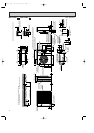
1.Slide the sleeve.
2.Pull the wire while
pushing the locking
lever.
OB207t-1qxp 25/9/97 8:52 PM Page 16