


En-6
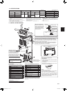
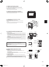
1)Removethepanel.
2)OpenthecoveroftheindoorcontrolP.C.board.
3)JointheconnectingcabletoCN105and/orCN104ontheindoorcontrolP.C.board.
4)Routetheconnectingcablethroughthispointinthegure.
5)Attachthecableclampprovidedwithinterface/connectorcabletothethickpartofthe
connectingcablewithascrew4×16asshowninthegure.
6)ClosethecoveroftheindoorcontrolP.C.board.Becarefulnottocatchthethinpart
oftheconnectingcableinthecover.Reinstallthepanel.
5)
4)
3)CN105
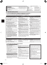
WARNING
Fix the connecting cable at the prescribed position securely.
Incorrect installation may cause electric shock, re, and/ or malfunction.
3. OUTDOOR UNIT INSTALLATION
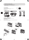
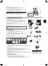
3-2. FLARING WORK
1)Cutthecopperpipecorrectlywithpipecutter.(Fig.1,2)
2)Completelyremoveallburrsfromthecutcrosssectionofpipe.(Fig.3)
•Puttheendofthecopperpipetodownwarddirectionasyouremoveburrsin
ordertoavoidtoletburrsdropinthepiping.
3)Removearenutsattachedtoindoorandoutdoorunits,thenputthemonpipehaving
completedburrremoval.(Notpossibletoputthemonafteraringwork.)
4)Flaringwork(Fig.4,5).Firmlyholdcopperpipeinthedimensionshowninthetable.
SelectAmmfromthetableaccordingtothetoolyouuse.
5)Check
•ComparethearedworkwithFig.6.
•Ifareisnotedtobedefective,cutoffthearedsectionanddoaringworkagain.
3-3. PIPE CONNECTION
• Fastenarenutwithatorquewrenchasspeciedinthetable.
• Whenfastenedtootight,arenutmaybreakafteralongperiodandcauserefrigerantleakage.
• Besuretowrapinsulationaroundthepiping.Directcontactwiththebarepipingmayresultinburnsor
frostbite.
Indoor unit connection
Connectbothliquidandgaspipingstoindoorunit.
• Applyathincoatofrefrigerationoil(J)onthearedendsofthepipes.Donotapplyrefrigerationoilon
screwthreads.Excessivetighteningtorquewillresultindamageonthescrew.
• Forconnection,rstalignthecenter,thentightentherst3to4turnsofarenut.
• Usetighteningtorquetableaboveasaguidelineforindoorunitsideunionjointsection,andtightenusing
twowrenches.Excessivetighteningdamagesthearesection.
Outdoor unit connection
Connectpipestostopvalvepipejointoftheoutdoorunitinthesamemannerappliedforindoorunit.
• Fortightening,useatorquewrenchorspannerandusethesametighteningtorqueappliedforindoorunit.
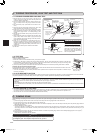
3-4. INSULATION AND TAPING
1)Coverpipingjointswithpipecover.
2)Foroutdoorunitside,surelyinsulateeverypipingincludingvalves.
3)Usingpipingtape(G),applytapingstartingfromtheentryofoutdoorunit.
•Stoptheendofpipingtape(G)withtape(withadhesiveagentattached).
•Whenpipinghavetobearrangedthroughaboveceiling,closetorwherethetemperatureandhumidity
arehigh,windadditionalcommerciallysoldinsulationtopreventcondensation.
Pipediameter
(mm)
Nut
(mm)
A(mm) Tighteningtorque
Clutchtype
tool
forR410A
Clutchtype
tool
forR22
Wingnut
typetool
forR22
N•m kgf•cm
ø6.35(1/4”) 17
0to0.5 1.0to1.5
1.5to2.0
13.7to17.7 140to180
ø9.52(3/8”) 22 34.3to41.2 350to420
ø12.7(1/2”) 26
2.0to2.5
49.0to56.4 500to575
- - - -
Copper
pipe
Good
TiltedUnevenBurred
Nogood
Fig.1 Fig.2
Burr
Copperpipe
Sparereamer
Pipecutter
Clutchtype
Flaringtool
Fig.4
Fig.3
Smoothall
around
Evenlength
allaround
Insideisshining
withoutany
scratches.
Flarenut
Die
Fig.5
Fig.6
Copper
pipe
Wingnuttype
WARNING
When installing the unit, securely
connect the refrigerant pipes before
starting the compressor.
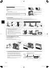
3-1. CONNECTING WIRES FOR OUTDOOR UNIT
1)Opentheservicepanel.
2)Loosenterminalscrew,andconnectindoor/outdoorunitconnectingwire(A)fromthe
indoorunitcorrectlyontheterminalblock.Becarefulnottomakemis-wiring.Fixthe
wiretotheterminalblocksecurelysothatnopartofitscoreisappeared,andnoex-
ternalforceisconveyedtotheconnectingsectionoftheterminalblock.
3)Firmlytightentheterminalscrewstopreventthemfromloosening.Aftertightening,
pullthewireslightlytoconrmthattheydonotmove.
4)Connectpowersupplycord(K).
5)Fixindoor/outdoorunitconnectingwire(A)andpowersupplycord(K)withthecord
clamp.
6)Closetheservicepanelsecurely.
• Makeearthwirealittlelongerthanothers.(Morethan100mm)
• Forfutureservicing,giveextralengthtotheconnectingwires.
• Besuretoattacheachscrewtoitscorrespondentterminalwhensecuringthecordand/or
thewiretotheterminalblock.
Terminalblock
Cordclamp
Terminalblock
Powersupply
cord(K)
15mm
35mm
Leadwire
<KJ25,35>
<KJ50,60>
Indoor/outdoor
unitconnecting
wire(A)
Power supply
cord (K)
Whenmountingthe
interfaceandthe
connectorcable,use
thisscrewtoxthe
connectingcable.
3)CN104
JG79A867H02_en.indd 6 2014/06/25 13:39:04