


En-5
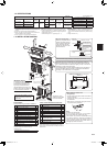
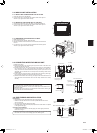
Donotmakedrainpipingasshownbelow.
Accumulated
drainwater
Air
Waving
Water
leakage
Donotraise
Water
leakage
Water
leakage
Tipofdrain
hosedipped
inwater
Ditch
Atleast
50mm
gap
Downward
slope
Drain
hose
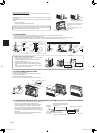
Softhose
I.D.15mm
Drainhose
Hardvinylchloride
pipeI.D.30mm
Insert
securely
Different
diameterjoint
70cmor
more
Fig.1 Fig.2 Fig.3
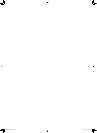
2-7. DRAIN PIPING
• Iftheextensiondrainhosehastopassthrougharoom,besuretowrapitwithcommerciallysoldinsulation.
• Thedrainhoseshouldpointdownwardforeasydrainow.(Fig.1)
• Ifthedrainhoseprovidedwiththeindoorunitistooshort,connectitwithdrainhose(I)thatshouldbeprovidedatyoursite.(Fig.2)
• Whenconnectingthedrainhosetothehardvinylchloridepipe,besuretoinsertitsecurelyintothepipe.(Fig.3)
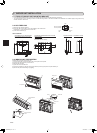
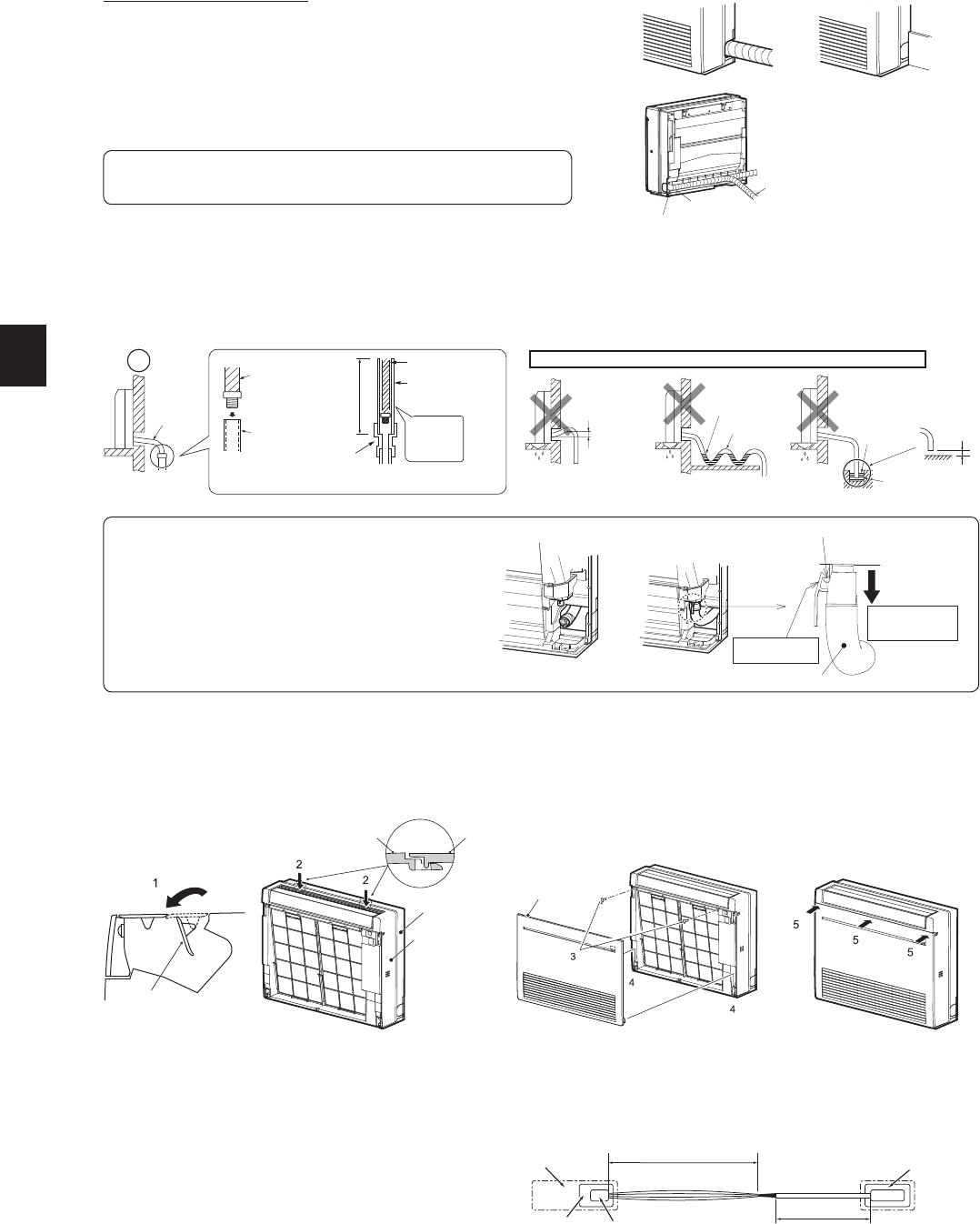
2-8. FRONT PANEL INSTALLATION
1)Opentherearhorizontalvane.
2)Attachthepanel.Makesurethatthecatchesareengaged.
3)Fixthepanelwithscrews.
4)Insertthebottompartofthefrontpanel.
5)Push3placesontheupperpartofthefrontpaneltocloseit.
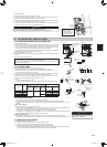
Wrapthefelttape(11)tightlyaroundthepipesandhosestartingnearwhere
thepipesandhoseareroutedfromtheindoorunit.(Theoverlapwidthofthefelt
tape(11)shouldnotbemorethan1/2ofthetapewidth.)
Felttape(11)
Startwrappingthepipingtape(G)around
thepipesandhose10mminsidethe
indoorunit.
Fastentheendofthefelttape(11)with
abandagestopper.
Makesurethatthedrainhose
isnotroutedupward.
FORLEFTORLEFT-REARPIPING
Bundletheconnectingpipesanddrainhosetogether,andthenwraptheminfelt
tape(11).
Cutandusethelowersidepanelsontheleftandrightsidesoftheindoorunitas
shownbelow.
Smooththecutedgesofthesidepanelssothattheywillnotdamagetheinsulation
coating.
• Forleftorrightpiping
• Installingushagainstawallwithmolding
Molding
Cutthelowersidepanelsto
matchtheheightofthemolding.
Fig.5
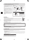
Projection
Makesureto
hookthecatch.
Drainhose
Pullthehoseto
conrmitiscon-
nectedsecurely.
Fig.4
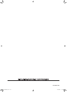
The Drain hose is removed at installation.
• Whenroutingthedrainpiping,makesurethatthedrain
hose(1)isroutedasshown.(Fig.4)
• Insertthedrainhoseallthewaytothebaseofthedrain
pan(endconnection).(Fig.5)
Makesurethatthecatchofthedrainhoseissecurely
hookedontotheprojectiononthehosettingofthedrain
pan.
• Afterconnectingthedrainhose,besuretopullthehoseto
conrmthatitisconnectedsecurely.
Frontpanel
Indoorunit
Indoorunit
Panel
Panel
2-9. CONNECTING AN INTERFACE (option)/CONNECTOR CABLE (option) TO THE AIR CONDITIONER
Thinpartoftheconnectingcable.
Placethispartwherecustomers
cannottouchit.
Roomair
conditioner
Mainbodyofaninterface
Thickpartoftheconnectingcable
Indoorcontrol
P.C.board
CN105forinterface
CN104forconnectorcable
•Connectaninterface/connectorcabletotheindoorcontrolP.C.
boardofanairconditionerwithaconnectingcable.
•Cuttingorextendingtheconnectingcableoftheinterface/
connectorcableresultsindefectsinconnecting.Donot
bundletheconnectingcabletogetherwithpowersupplycord,
indoor/outdoorconnectingwire,and/orearthwire.Keepas
muchdistanceaspossiblebetweentheconnectingcableand
thosewires.
•Thethinpartoftheconnectingcableshouldbestoredand
placedwherecustomerscannottouchit.
Rearhorizontal
vane
JG79A867H02_en.indd 5 2014/06/25 13:39:01