


En-2
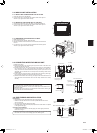
Indoorunit
Wallhole
sleeve(C)
Cutofftheextra
length.
Pipexingband
(E)
Wallholecover(D)
Sealthewallhole
gapwithputty(H).
Fixthepipetowall
withpipexing
band(E).
Fixingscrew
(F)
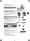
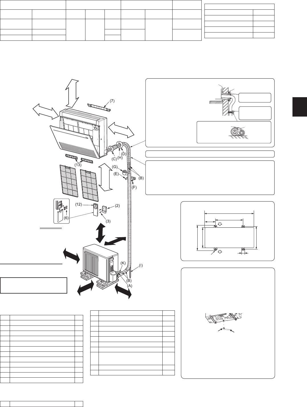
1-3. SPECIFICATIONS
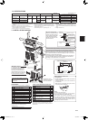
1-4. INSTALLATION DIAGRAM
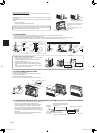
ACCESSORIES
Checkthefollowingpartsbeforeinstallation.
(1) Drainhose* 1
(2) Remotecontrollerholder 1
(3) Fixingscrewfor(2)3.5×16mm(Black) 2
(4) Pipecover 1
(5) Band 2
(6) Battery(AAA)for(12) 2
(7) Indoorunitmountingbracket 1
(8) Fixingscrewfor(7)4×25mm 5
(9) Woodscrewforindoorunitxation 4
(10) Washerof(9) 4
(11) Felttape(Forleftorleft-rearpiping) 1
(12) Wirelessremotecontroller 1
(13) Aircleaninglter 2
* Note:
TheDrainhoseisconnectedtotheunit.
<Outdoorunit>
(14) Drainsocket(VEtypeonly) 1
Unitsshouldbeinstalledbylicensed
contractoraccordingtolocalcode
requirements.
Aftertheleaktest,applyinsulatingmaterialtightlysothatthereisnogap.
Besuretousewallhole
sleeve(C)topreventindoor/
outdoorconnectingwire(A)
fromcontactingmetalparts
inthewallandtoprevent
damagebyrodentsincase
thewallishollow.
PARTS TO BE PROVIDED AT YOUR SITE
(A) Indoor/outdoorunitconnectingwire* 1
(B) Extensionpipe 1
(C) Wallholesleeve 1
(D) Wallholecover 1
(E) Pipexingband 2to5
(F) Fixingscrewfor(E)4×20mm 2to5
(G) Pipingtape 1
(H) Putty 1
(I)
Drainhose
(orsoftPVChose,15mminnerdia.or
hardPVCpipeVP16)
1 or 2
(J) Refrigerationoil 1
(K) Powersupplycord* 1
* Note:
Placeindoor/outdoorunitconnectingwire(A)and
powersupplycord(K)atleast1mawayfromtheTV
antennawire.
150mmorbelow
fromtheoor
100
mm
or
more
Noobstruction
100
mm
or
more
*1Connecttothepowerswitchwhichhasagapof3mm
ormorewhenopentointerruptthesourcepowerphase.
(Whenthepowerswitchisshutoff,itmustinterruptall
phases.)
*2Usewiresinconformitywithdesign60245IEC57.
*3Neverusepipeswiththicknesslessthanspecied.The
pressureresistancewillbeinsufcient.
*4Useacopperpipeoracopper-alloyseamlesspipe.
*5 Becarefulnottocrushorbendthepipeduringpipebend-
ing.
*6Refrigerantpipebendingradiusmustbe100mmormore.
*7Ifpipelengthexceeds7m,additionalrefrigerant(R410A)
chargeisrequired.(Noadditionalchargeisrequiredfor
pipelengthlessthan7m.)
Additionalrefrigerant=A×(pipelength(m)–7)
*8Insulationmaterial:Heatresistingfoamplastic0.045
specicgravity
*9Besuretousetheinsulationofspeciedthickness.Ex-
cessivethicknessmaycauseincorrectinstallationofthe
indoorunitandinsufcientthicknessmaycausedewdrip-
page.
*10
Singleconnectiononly.
Model Powersupply*1 Wirespecications*2
Pipesize
(thickness*3,*4)
Indoorunit Outdoorunit
Rated
Voltage
Frequency
Breaker
capacity
Powersupply
(3-core)
Indoor/outdoor
connectingwire
Gas/Liquid
MFZ-KJ25VE
MFZ-KJ35VE
MUFZ-KJ25VE
MUFZ-KJ35VE
230V 50Hz
10A 1.0mm
2
4-core
2.0mm
2
ø9.52/6.35mm
(0.8mm)
MFZ-KJ50VE MUFZ-KJ50VE(HZ) 16A
2.0mm
2
ø12.7/6.35mm
(0.8mm)
MFZ-KJ60VE
*10
MUFZ-KJ60VE(HZ) 20A
(KJ25,35/KJ50,60)
Pipelengthandheightdifference
Max.pipelength 20/30m
Max.heightdifference 12/15m
Max.numberofbends*5,*6 10
RefrigerantadjustmentA*7 30/20g/m
Insulationthickness*8,*9
8mm
(KJ25,35/KJ50,60)
100/500mmormore
100
mm
ormore
(KJ25,35/KJ50,60)
200/500mmormore
350
mm
ormore
100
mm
or
more
Appearanceofthe
outdoorunitmaydiffer
fromsomemodels.
Airinlet
Airoutlet
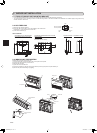
Outdoor unit installation
(KJ25,35/KJ50,60)
2/4-10mm×21mmslot
800/840mm
150/175
mm
500mm
344.5/390mm
285/330mm
304-325/349-371mm
40mm
Whenthepipingistobeattachedtoawallcontainingmetals(tin
plated)ormetalnetting,useachemicallytreatedwoodenpiece20
mmorthickerbetweenthewallandthepipingorwrap7to8turnsof
insulationvinyltapearoundthepiping.
Touseexistingpiping,performCOOLoperationfor30minutesand
pumpdownbeforeremovingtheoldairconditioner.Remakeare
accordingtothedimensionfornewrefrigerant.
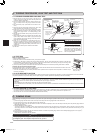
Drain piping for outdoor unit
<VE type only>
•Providedrainpipingbeforeindoorandoutdoor
pipingconnection.
•Connectdrainhose(I)I.D.15mmasshownin
theillustration.
•Makesuretoprovidedrainpipingwithadown-
hillgradeforeasydrainow.
(14)
(I)
Note:
Installtheunithorizontally.
Donotusedrainsocket(14)incoldregions.
Drainmayfreezeandmakethefanstop.
Theoutdoorunitproducescondensateduring
theheatingoperation.Selecttheinstallation
placetoensuretopreventtheoutdoorunitand/
orthegroundsfrombeingwetbydrainwateror
damagedbyfrozendrainwater.
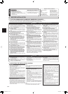
IMPORTANT NOTES
Tocomplywiththerequirements
ofAustralianstandardAS/NZS
3000electricalinstallations(wir-
ingrules),theelectricalwiring
requiredbetweentheindoorand
outdoorunitsmustbeinstalledby
alicencedelectricalcontractor.
JG79A867H02_en.indd 2 2014/06/25 13:38:52