


18
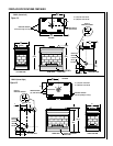
NOTE: DIAGRAMS & ILLUSTRATIONS NOT TO SCALE.
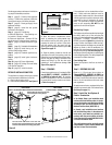
Figure 34
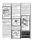
Step 9. Reassemble the remaining compo-
nents by reversing the procedures outlined in
the preceding steps. Use pipe joint compound
or Teflon tape on all pipe fittings before install-
ing (ensure propane resistant compounds are
used in propane applications, do not use pipe
joint compounds on flare fittings).
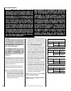
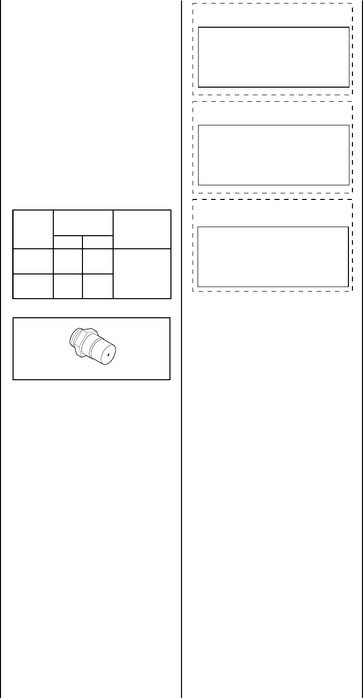
Step 10. Attach the conversion label provided
in the conversion kit to the rating plate on the
appliance.
Figure 35
shows all of the labels for
all of the kits covered by this manual as shown
in the tables on page 17. Compare the label
provided in the kit being installed to the appro-
priate label shown in
Figure 35
.
Step 11. Turn on the gas supply and test for
leaks as shown in
step 5 on page 11
.
Figure 35
All Models
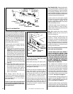
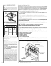
Step 8.
(Refer to Figure 29 )
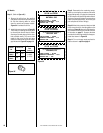
A. Remove the orifice from the manifold
and replace it with the one provided in the
kit. See the following table for orifice
sizes for natural and propane models
.
Figure 34
illustrates the orifice.
B. Install the burners as shown in
Figure 29
.
The primary air opening can be adjusted
by removing the venturi tube air shutter
securing screw and placing it in the other
hole provided nearby. The correct hole
usage for this screw for the gas being
used can be determined by the air shutter
gap indicated in
Figure 25 on page 14.
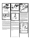
ledoM
.oN
ezisecifirO
noitavelE
teeF
)sretem(
.taN.porP
TSVBE
FPVBE
23#05#
0054-0
)2731-0(
RCVBE
LCVBE
43#05#
THIS APPLIANCE HAS BEEN CONVERTED TO:
NATURAL GAS
INPUT BTU/HR – 37,500
MANIFOLD PRESSURE – 3.5"
ORIFICE SIZE – #32
Kit Catalog No.
H2199 and H2201
Kit Catalog No.
H2198 and H2200
THIS APPLIANCE HAS BEEN CONVERTED TO:
PROPANE/LPG
INPUT BTU/HR – 34,000
MANIFOLD PRESSURE – 10.0"
ORIFICE SIZE – #50
THIS APPLIANCE HAS BEEN CONVERTED TO:
NATURAL GAS
INPUT BTU/HR – 34,000
MANIFOLD PRESSURE – 3.5"
ORIFICE SIZE – #34
Kit Catalog No.
H2203 and H2205