


17
NOTE: DIAGRAMS & ILLUSTRATIONS NOT TO SCALE.
Pressure
Regulator
Remove
These
Components
Pilot
Orifice
Spring
Adjusting
Screw
Slotted
Cap
P
S
I
OFF
I
ON
CONTROL
I
G
N
I
T
E
Manifold
Pressure
Test Port
Inlet Pressure Test Port
Retaining
Clip
Ignitor
Assembly
Pilot
Assembly
Pilot
Orifice
Flare Nut
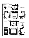
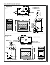
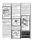
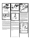
BACK OF FIREPLACE
PAN BURNER
FIREBOX BOTTOM
BURNER POSITIONING
PAN
BURNER
PILOT ASSEMBLY
Figure 33
Figure 32
Figure 31
Figure 30
Figure 29
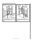
When reinstalling the ignitor assembly, use
extreme care to prevent damage and break-
age. Do not apply any leverage to the ignitor
assembly while restoring the retainer clip to
its original position.
Note: If the ignitor is damaged, a replace-
ment kit is available, order Catalog Number
87L54.
Electronic Appliances
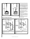
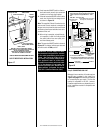
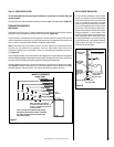
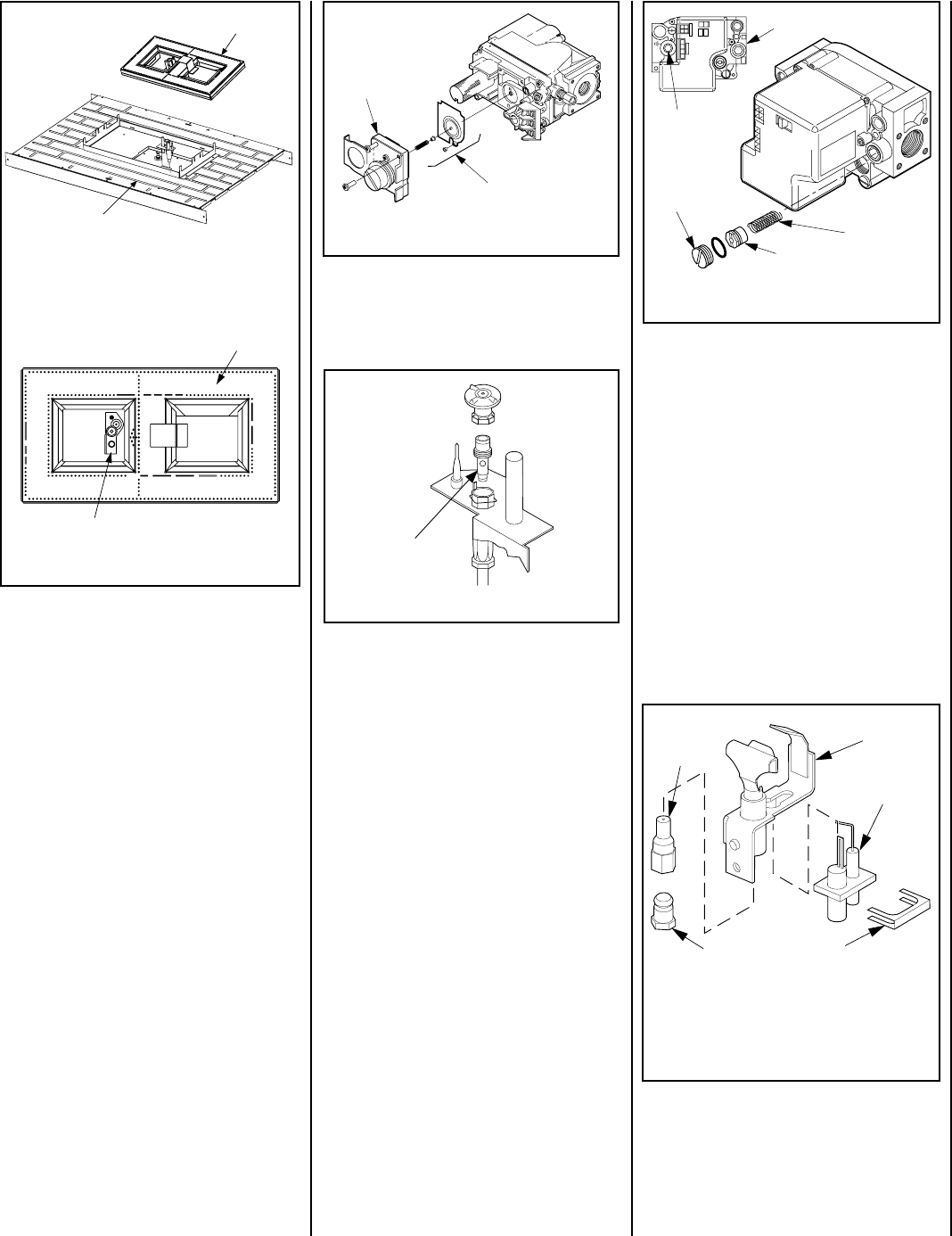
Step 7. Honeywell Electronic Valves - See
Figure 32
and the instructions provided with
the kit. Remove the slotted cap screw, o-ring,
pressure-regulating adjusting screw and
spring. Retain all parts for possible later use.
Install new components from the kit. Black
cap and red spring for propane gas units.
Silver cap and stainless steel spring fro natural
gas units.
Before installing the cap, attach manometer
to the manifold side pressure test fitting and
adjust screw until pressure reads 3.5 inches
water column (0.87 kPa) for natural gas, and
10.0 inches water column (2.49 kPa) for
propane gas.
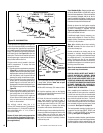
See
Figure 33
and replace the pilot orifice as
follows: Remove the ignitor assembly retainer
clip, and carefully remove the ignitor assembly.
Exercise extreme care to prevent damage to
or breakage of the ignitor assembly. Remove
the screw securing the pilot assembly to its
mounting bracket. Back off the flare nut at the
end of the pilot gas line to free the pilot assem-
bly from the gas line. Remove the pilot orifice
and replace it with the one provided with the
conversion kit. Reinstall the pilot assembly by
reversing the steps detailed here.
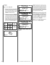
Step 6. Refer to
Figure 31
and remove the
pilot hood assembly to access the hexed pilot
orifice. Remove and replace the orifice with
the one provided with the kit.
Millivolt Appliances
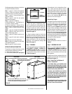
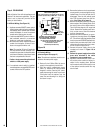
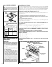
Step 4. SIT Systems - Refer to
Figure 30
and
the instructions provided with the kit. Using a
Torx T20, remove and discard the three pres-
sure regulator mounting screws. Remove the
pressure regulator, spring, poppet, diaphragm
and bushing. Discard all removed compo-
nents. Ensure the rubber gasket installed on
the back of the replacement pressure regulator
is properly positioned and install the new pres-
sure regulator using the new screws supplied
with the kit. Tighten screws to 25 In. lb. torque.
Step 5. Attach manometer to the manifold side
pressure test fitting and verify manifold pres-
sure reads 3.5 inches water column (0.87 kPa)
for natural gas, and 10.0 inches water column
(2.49 kPa) for propane gas.