


13
NOTE: DIAGRAMS & ILLUSTRATIONS NOT TO SCALE.
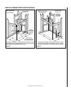
Figure 24
-
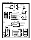
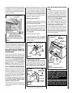
Installing the Glass Enclosure Panel
Glass
Enclosure
Panel
Latch
Lower Compartment Door and Hinge
Front Glass
Enclosure Panel
Firebox
Floor
Bottom Vee-flanges
(Glass Enclosure
Panel Frame)
Top Flange
(Glass Enclosure
Panel Frame)
Modesty Panel
EBVST SHOWN
WARNING: HANDLE THE GLASS WITH
EXTREME CARE! TEMPERED GLASS IS
SUSCEPTIBLE TO DAMAGE (SCRATCHES,
FOR EXAMPLE) – HANDLE GLASS DOOR
(GLASS ENCLOSURE PANEL) GENTLY
WHILE REINSTALLING IT.
WARNING: NEVER OPERATE THE APPLI-
ANCE WITHOUT THE FRONT GLASS EN-
CLOSURE PANEL IN PLACE AND SECURE.
Figure 22
Figure 23
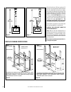
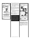
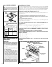
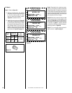
The top ³⁄₈" (10 mm) at the pilot generator
(thermopile) and the top ¹⁄₈" min (tip) of the
quick drop out thermocouple should be en-
gulfed in the pilot flame. The flame should
project 1" (25 mm) beyond the hood at all three
ports
(Figure 22)
.
Millivolt Appliance Checkout
The pilot flame should be steady and, not lifting
or floating. Flame should be blue in color with
traces of orange at the outer edge.
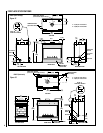
Step 7. INSTALLING LOGS, VERMICULITE,
DECORATIVE VOLCANIC STONE AND
GLOWING EMBERS
The log set is located within the firebox. One
plastic bag of glowing embers, one plastic bag
of decorative volcanic stone and one bag of
vermiculate, is located in the bottom compart-
ment. Refer to the Log Placement Guide for
detailed placement instructions for the log set
and glowing embers. See the Homeowners
Manual for placement instructions of vermicu-
late, decorative volcanic stone and rockwool.
Step 8. CHECKING APPLIANCE OPERATION
With gas line installed run initial system check-
out before closing up the front of the unit.
Follow the pilot lighting instructions provided
in the Homeowner's Care and Operation In-
structions. For piezo ignitor location see
Figure
20 on page 12
(millivolt appliances only).
Note: Lighting instructions may also be found
on the pull out lighting instruction labels
attached to the gas control valve.
Step 9. INSTALLING GLASS ENCLOSURE
PANELS
Electronic Appliance Checkout
To light the burner, turn ‘ON’ the modesty
panel mounted ON/OFF switch and turn the gas
control switch to the “ON” position. Ensure the
ignitor lights the pilot. The pilot flame should
engulf the flame rod as shown in
Figure 23
.
Replace logs after pilot inspection.
To light the burner; turn “ON” the modesty
panel mounted ON/OFF switch and rotate the
gas valve control knob counterclockwise to
the “ON” position.
When first lighting the appliance, it will take
a few minutes for the line to purge itself of
air. Once purging is complete, the pilot and
burner will light and operate as indicated in
the instruction manual. Subsequent lightings
of the appliance will not require such purg-
ing. Inspect the pilot flame (remove logs, if
necessary, handling carefully).
1. Visually inspect the gasket on the backside
of the panels. The gasket surface must be
clean, free of irregularities and seated firmly.
2. Position the glass enclosure panel in front
of the firebox opening at a 45 degree angle and
engage the top flange over the lip at the top of
the firebox opening.
See Figure 24.
3. Swing the glass enclosure panel down and
back. Ensure the gasket seats evenly as the
panel draws shut. Engage the Vee-flanges at
the bottom of the panel with the latches; then
close the latches to secure the panel.
4. After installing the front glass enclosure
panel, reinstall the bottom control compart-
ment access panel by inserting the right side
locating pin into the right side cabinet panel
and then the left side spring-loaded pin into
the left side cabinet panel.
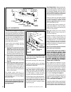
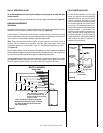
Figure 21
Operate the actuator through several cycles
including the closed position. Ensuring proper
operation and freedom of movement. Return
the actuator arm to the closed position.
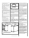
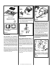
Outside Air Control Lever
and Securing Screw Location
(EBVST, EBVPF and EBVCR Units Shown)
The outside air shutter should be fully open when
the fireplace is in use and completely closed
when the fireplace is not being used. Closing it
when not in use will prevent outside cold air from
entering the dwelling.
To access the label, see the procedure on the
previous page described for accessing the gas
control valve.
MILLIVOLT
Thermocouple
Hood
Ignitor Rod
³⁄₈" Min
(9 mm)
Thermopile
Pilot
Nozzels
ELECTRONIC
Proper Flame
Adjustment
Pilot
Nozzle
3/8 To 1/2 Inch
(9 mm to 13 mm)
Ground
Electrode
Flame Rod
Hot Surface
Igniter
Outside Air Control Lever with Stop Behind
Securing Screw
Outside Air Shutter in the
Closed Position
Control Compartment Access Panel