


10
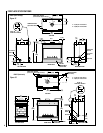
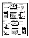
NOTE: DIAGRAMS & ILLUSTRATIONS NOT TO SCALE.
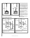
Step 4. FIELD WIRING
Refer to Section A for millivolt appliances and
Section B for electronic appliances. The gas
valve is set in place and pre-wired at the
factory on both models.
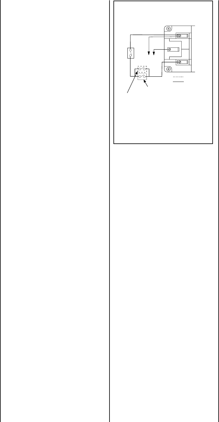
A. Millivolt Wiring
(See Figure 16 )
1. Appliance-mounted ON/OFF burner control
switch (rocker switch) is factory installed in
the modesty panel. Optional wall-mounted
switch, thermostat, or one of the optional
remote control kits may also be used.
2. If wall-mounted ON/OFF control or thermo-
stat is selected, mount it in a convenient
location on a wall near the fireplace.
3. Wire the control switch within the millivolt
control circuit using the 15 feet of 2 con-
ductor wire supplied with the unit.
Note: The supplied 15 feet of 2 conductor
wire has one end of each conductor con-
nected to the gas valve circuit and the other
end of each conductor placed loose inside
the lower compartment of the unit.
Caution: do not connect the optional wall
switch to a 120V power supply.
4. If an optional control switch is installed,
turn the appliance-mounted ON/OFF burner
control switch to the OFF position.
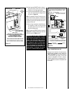
Figure 16
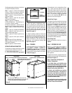
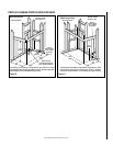
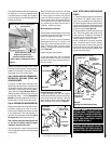
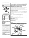
3. Remove the bottom control compartment
access panel by compressing the spring-
loaded hinge pin on the left side until it
disengages from the left cabinet panel
hole. Pull the panel away from the fire-
place.
See Figure 20 on page 12.
4. Remove the modesty panel by pulling the
bottom edge of the modesty panel out of
the locking slots of the cabinet bottom.
Then tilt the top edge at a 45° angel and
lift out. Remove the modesty panel care-
fully, so that none of the wires become
loose or disconnected.
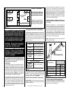
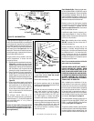
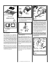
5. Remove the outlet receptacle by remov-
ing the two securing screws. See
Figure
17.
(The left and right designations used
here are reversed in EBVCR applications.)
6. Install a field-provided strain relief in the
cabinet knockout opening for the protec-
tion of the power supply wires.
7. Connect the power supply wires to the
receptacle as shown in
Figure 18 on
page 11.
8. Connect the ground supply wire and the
green wire attached to the outlet
receptacle's green ground screw.
9. Appliance-mounted ON/OFF burner con-
trol switch (rocker switch) is factory in-
stalled in the modesty panel. Optional
wall-mounted switch, thermostat, or one
of the optional remote control kits may
also be used.
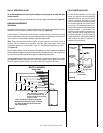
Thermopile
TH
TP
TH
TP
White
White
Black
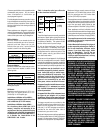
Millivolt Wiring Diagram
If any of the original wire as supplied must be replaced,
it must be replaced with Type AWM 105°C – 18 GA. wire.
*OPTIONAL WALL-MOUNTED ON/OFF
SWITCH OR OPTIONAL THERMOSTAT
OR OPTIONAL REMOTE RECEIVER
*Turn the appliance-mounted ON/OFF burner control
switch to the OFF position if an optional
control switch is installed.
Factory Wired
Field Wired
Schematic Representation Only
APPLIANCE-MOUNTED ON/OFF SWITCH
LIMIT SWITCH
B. Electronic Wiring
(also see Figure 18 on page 11 )
Note: The electronic appliance must be con-
nected to the main power supply.
1. Route a 3-wire 120Vac 60Hz 1ph power
supply to the appliance junction box.
2. Open the control compartment access
panel, by actuating the spring-loaded
magnetic catches securing the panel,
gently depressing the outer top corners
of the panel until the catches "pop" the
panel free and allowing it to swing out
and down to open.