


11
NOTE: DIAGRAMS & ILLUSTRATIONS NOT TO SCALE.
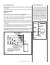
Note: The gas valve ON/OFF switch is shown in
Figure 18. It is integral with the gas valve and
should be set to the ON position.
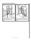
10. If wall-mounted ON/OFF switch or thermo-
stat is to be used, mount it in a convenient
location on a wall near the fireplace.
11. If the wall-mounted ON/OFF switch is to be
used, wire it to the the low voltage circuit
as shown in
Figure 18.
Note: The supplied 15 feet of 2 conductor wire
has one end of each conductor connected to
the gas valve circuit and the other end of each
conductor placed loose inside the lower com-
partment of the unit.
12. After wiring is complete, reinstall the out-
let receptacle; install the field-provided
the metal junction box cover plate; rein-
stall the modesty panel.
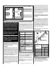
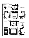
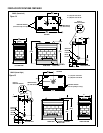
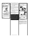
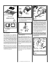
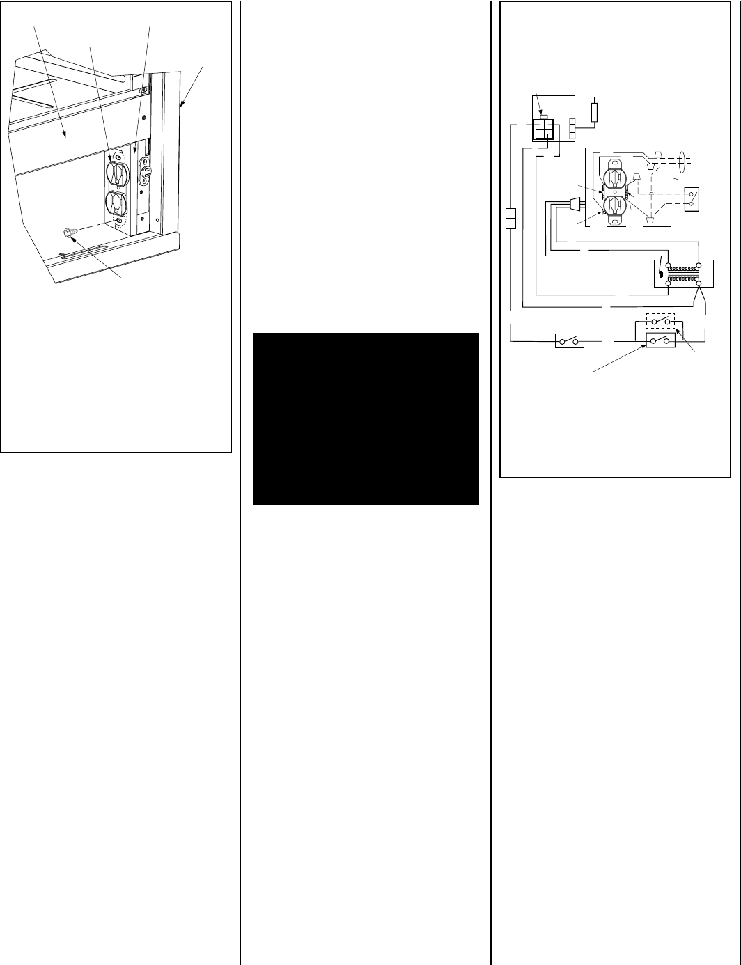
OUTLET RECEPTACLE INSTALLATION
Figure 17
EBST-2, EBPF-2
AND EBCL-2 OUTLET RECEPTACLE SHOWN.
EBCR-2 HAS THE OUTLET RECEPTACLE LOCATED IN
THE LEFT CORNER OF THE UNIT
EBBAY OUTLET RECEPTACLE LOCATED IN
THE REAR LEFT CORNER OF THE UNIT
VIEW OF RIGHT BOTTOM CORNER OF UNIT
OUTLET RECEPTACLE
JUNCTION BOX
OUTLET RECEPTACLE
BOX SECURING SCREW
CABINET
RIGHT SIDE
PANEL
FIREBOX BOTTOM
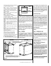
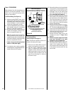
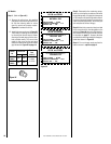
IMPORTANT: Ground supply wire must
be connected to the green wire attached
to the outlet receptacle's green ground
screw. See
Figure 18
. Failure to do so
will result in a potential safety hazard.
The appliance must be electrically
grounded in accordance with local codes
or, in the absence of local codes, the
National Electrical Code, ANSI/NFPA 70-
(latest edition). (In Canada, the current
CSA C22-1 Canadian Electrical Code.)
Step 5. CONNECTING GAS LINE
Make gas line connections. All codes require a
shut-off valve mounted in the supply line.
Figure 19 on page 12
illustrates two methods
for connecting the gas supply. The flex-line
method is acceptable in the U.S., however,
Canadian requirements vary depending on lo-
cality. Installation must be in compliance with
local codes.
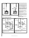
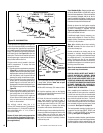
Figure 18
1. If any of the original wire as supplied must be replaced,
1. it must be replaced with Type AWM 105°C – 18 GA.
wire.
2. 120V, 60Hz – Less than 3 amps.
BK
Transf.
120 V.
24 V
Factory Wired Field Wired
BL
Electronic Wiring Diagram (Honeywell)
R
WT
BL
W
Gas Valve
B
APPLIANCE-MOUNTED ON/OFF SWITCH
R
IGNITER
PILOT
ASSEMBLY
BK
Schematic Representation Only
*ON/OFF Switch (Integral
with Gas Valve)
**OPTIONAL WALL SWITCH
OR OPTIONAL THERMOSTAT
OR OPTIONAL REMOTE
RECEIVER
*Leave the ON/OFF switch, which is integral
with the gas valve, in the ON position.
**Turn the appliance-mounted ON/OFF burner control switch to
the OFF position if an optional control switch is installed.
LIMIT SWITCH
WT
G
Junction Box
White
Green
Red
Black
Neutral
Side of
Receptacle
Tab Intact
Green
Ground
Screw
Hot
Side of
Receptacle
Tab
Broken
120 VAC - Black
n
e
e
r
G-dn
u
o
r
G
Optional
Accessory
Switch
e
ti
h
W
-
lar
t
u
e
N