


key. (e.g. living room lamp, TV, garden lights,
etc.).
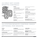
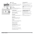
8. BATTERY COMPARTMENT (BACK COVER)
INSTALLATION:
1. PLACING THE BATTERIES
IMPORTANT: When placing the batteries, make
sure the switch is not in position 2!
Open the battery compartment on the back of
the remote control and place the batteries (4 x
AAA, preferably use alkaline batteries). Make sure
you observe the instructions in the battery
compartment. Replace the battery cover.
2.
ACTIVATION OF THE SH624 (install mode)
Press the PANIC key until the control indicator
comes on. Set the mode switch to the SEC
position. Make also sure that the House Code is on
the same letter code as the base station (behind
the cover).
11MS9470/MS9770/MS9970
4.7
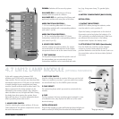
LM12 LAMP MODULE (OPTIONAL FOR MS9470)
2
3
4
1
3
7
5
4
1
6
2
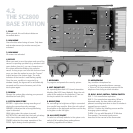
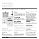
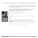
DISARM: Switches off the security system.
ALL LAMPS ON: for switching on all lamp
modules with one press of a button.
ALL LAMPS OFF: for switching off all (lamp and
appliance) modules with one press of a button.
MODE SWITCH IN POSITION 1:
1…8: For controlling Marmitek X-10 Home
Automation modules with corresponding address
(unit code 1 t/m 8).
MODE SWITCH IN POSITION 2:
9…16: For controlling Marmitek X-10 Home
Automation modules with corresponding address
(unit code 9 t/m 16).
6. HOUSE CODE SWITCH
Used for setting the system address. For proper
communication, all code switches of the system
components have to set to the same House Code.
7. TEXT WINDOW
On the piece of paper behind the plastic cover of
the text window, you can note which Home
Automation modules can be controlled with each
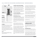
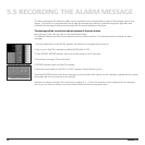
Lights with a power rating between 40W
minimum and 300W can be connected to the
lamp module. Do not connect any other load -like
household equipment or CFL lights- to the module
to avoid damage to your equipment and lamp
module. Special modules exist for other loads. The
lights connected to the lamp module can be
activated by the remote controls. Also, when an
alarm situation occurs, the lights will flash. During
the delay time when arming the system, these
lights will also be on. For more information about
what is possible, please refer to 6.8.
1. HOUSE CODE SWITCH
Used for selecting the system address. All House
Code Switches of the system components need to
be set to the same code.
2. UNIT CODE SWITCH
Used for setting the module number. When you set the Unit
Code on a module to number 3, you can switch the module
on and off with key 3 on the SH624 system remote.
3. PLUG SOCKET
For connecting lamps which you want to control with the
module.
4. FUSE
The fuse protects the lamp module against overload. In case
of a defective fuse, only replace this with one of the same
electrical ratings.
INSTALLATION LM12
Plug the lamp module in a spare wall socket and plug the lights you
want to control (40-300W) into the socket of the lamp module. *Plug type may vary