SERVICING
mini HE --- Installation & Servicing 47
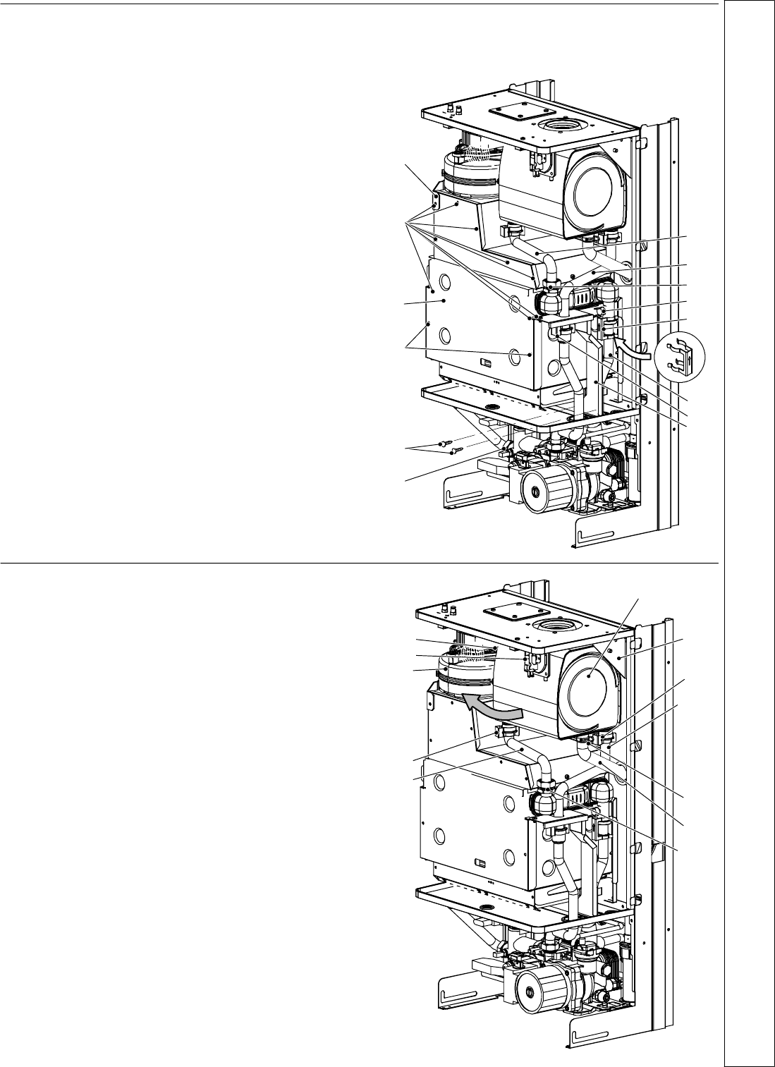
67 PRIMARY HEAT EXCHANGER
REPLACEMENT
1 Disconnect the electrical supply .
2 Remove outer and inner casing as explained in frame 42.
3 Close off the isolating cocks of the CH circuit at the
bottom of the boiler.
4 R elease system pressure by opening the main circuit
drainage cock. Do not release CH pressure using the
pressure relief valve. It may cause debris within the
system to foul the valve.
5 Remove the combustion chamber panel A by unscrewing
the screws B and removing the fan holder bracket C.
6 Remove the screws D and the plate E.
7 L oosen the connection F and slightly move the pipe G
upwards.
8 Remove the clip H and the safety thermostat I. It is not
necessary to disconnect it from the wiring.
9 Completely unscrew the c onnection J and move the pipe
K downwards freeing it from the heat exchanger
connection.
10 Remove the clip L.
11 Move the pipe M upwards freeing it from the connection
and rotate towards right.
12 Remove the heat exchanger by sliding it forwards.
13 Re---assemble in reverse order.
Fit the clip H with the arrow pointing upwards as
illustrated in the drawing.
Do not force the connection F when tighting it.
D
L
B
A
E
B
C
F
H
I
M
J
K
G
68 RECUPERATOR REPLACEMENT
1 Disconnect the electrical supply .
2 Remove outer and inner casing as explained in frame 42.
3 Close off the isolating cocks of the CH circuit at the
bottom of the boiler.
4 R elease system pressure by opening the main circuit
drainage cock.
Do not release CH pressure using the pressure relief
valve. It may cause debris within the system to foul
the valve.
5 Remove the fan A (see frame 58) and the air pr e ssure
switch B (see frame 60).
6 Remove the flue temperature probe
C (see frame 53)
7 Completely loosen the connection D and slightly move the
pipe E upwards.
8 RemovetheclipFandmovethepipeGdownwards
freeing it from the connect ion, then turn it towards right.
9 Using pliers, remove the spring H moving it downwards
and disconnect the rubber pipe I.
10 Remove the bracket J by unscrewing the scr ews that hold
it on the frame.
11 Rotate the recuperator K as indicated by the arrow and
remove it towards the front of the boiler.
12 RemovetheclipLandthepipeE.
13 Reassemble the recuperator carrying out the removal
operations in reverse order.
After reassembling ensure that the fan---exchanger and
exchanger---elbow gaskets are correctly mounted and
ensure a good sealing.
A
B
C
D
F
H
I
J
K
G
L
E
SERVICING


