


GENERAL
mini HE --- Installation & Servicing
11
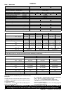
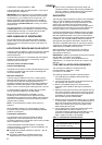
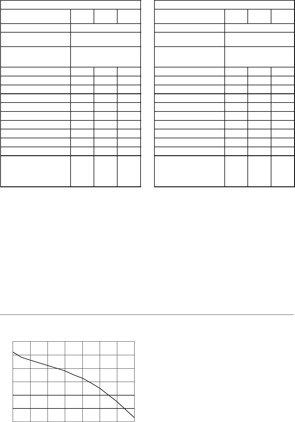
Table 5 mini HE C24, mini HE C28
System charge pressure
(bar)
0.5 0.7 1.0
Safety valve setting 3.0
V essel pre---charge pressure
(bar)
0.7
System volume (litres) Volume of expansion vessel
in addition to 6 litre unit
fitted to boiler
75 --- --- ---
100 0.3 0.8 1.4
125 1.8 2.5 3.2
150 3.4 4.2 5.0
175 5.0 6.0 7.0
200 6.5 7.6 8.7
225 8.1 9.3 10.6
250 9.6 11.1 12.4
275 11.2 12.8 14.3
300 12.8 14.5 16.1
Multiply this factor by
system volume and deduct
6 litres to obtain size of
additional vessel for other
system volumes.
0.063 0.069 0.074
5 Size of expansion vessel
For the system water expansion to be contained by the 6 litre
expansion vessel fitted t o the following models:
mini HE C24, mini HE C28
the cold system volume must not exceed:
96 litres when pressurised to 0.5 bar (cold)
88 litres when pressurised to 0.7 bar (cold)
81 litres when pressurised to 1.0 bar (cold)
If the pressure exceeds 2.65 bar when the boiler is up to
temperature with all radiators in use then an additional
expansion vessel MUST be installed o n the return pipework.
For expansion volumes see Table 5.
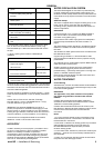
Tab le 6 m ini HE C 32
System charge pressure
(bar)
0.5 0.7 1.0
Safety valve setting 3.0
V essel pre---charge pressure
(bar)
0.7
System volume (litres) Volume of expansion vessel
in addition to 7 litre unit
fitted to boiler
75 --- --- ---
100 --- --- 0.4
125 0.8 1.6 2.3
150 2.5 3.4 4.1
175 4.0 5.1 6.0
200 5.6 6.8 7.8
225 7.2 8.6 9.7
250 8.8 10.3 11.5
275 10.3 12.0 13.4
300 11.9 13.7 15.2
Multiply this factor by
system volume and deduct
7 litres to obtain size of
additional vessel for other
system volumes.
0.063 0.069 0.074
For the system water expansion to be contained by the 7 litre
expansion vessel fitted t o the following model:
mini HE C32
the cold system volume must not exceed:
111 litres when pressurised to 0.5 bar (cold)
101 litres when pressurised to 0.7 bar (cold)
95 litres when pressurised to 1.0 bar (cold)
If the pressure exceeds 2.65 bar when the boiler is up to
temperature with all radiators in use then an additional
expansion vessel MUST be installed o n the return pipework.
For expansion volumes see Table 6.
Guidance on vessel sizing is given in BS 7074:1 and BS 5449
For IE refer to the current edition of I.S. 813.
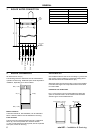
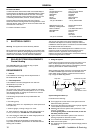
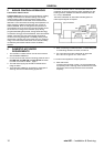
6 Hydraulic Loss
Remaining pump capacity
0
1
2
3
4
5
6
0 200 400 600 800 1000 1200 1400
Flow rate l/hour
mH2O
7 Draining the system
Draining taps MUST be located in accessible positions to
permit the draining of the whole central heating system,
including the central heating side of the boiler. The taps
should be at least 1/2” BSP nominal size and be in
accordance with BS 2879.