SERVICING
mini HE --- Installation & Servicing38
REPLACEMENT OF COMPONENTS
48 GENERAL
When replacing any component:
1 I solate the electricity supply at the switched spur.
N.B. Turning the boiler “ON/OFF” switch does not isolate
the live supply to the boiler.
2 Turn off the gas supply.
IMPORTANT. When work is complete the inner case cover
must be correctly fitted, ensuring that a good seal is made.
THE BOILER MUST NOT BE OPERATED IF THE INNER
CASE COVER IS NOT FIT TED.
If the CH and/or the DHW circuits have been emptied:
3 O pen the hydraulic circuit cocks, refill / re---pressurise
pipeworks and vent the system.
4 Test fire the boiler
5 Disconnect the filling l oop.
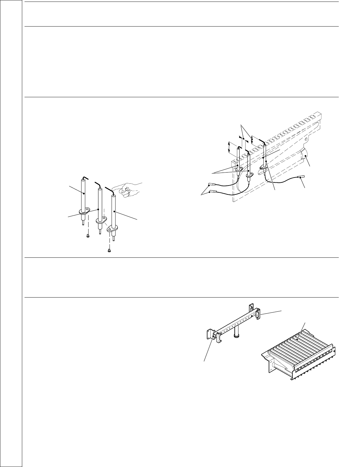
49 SPARK AND DETECTION
ELECTRODE REPLACEMENT
1 Disconnect the electrical supply .
2 Remove outer and inner casing (r efer to frame 42).
3 Open the combust ion chamber and disconnect the
electrodes leads.
4 Remove the burner. Refer to frame 43.
5 Undo the screws that hold the electrodes and remove.
6 Fit new electrodes as necess ary following the sequence
illustrated.
Ignition 1
st
Ignition 2
nd
Detection 3
rd
7 Check the spark gap.
4 mm (5/32”)
Ignition
Detection
Male
Female
10 mm
Burner blade
(3/8”)
8 Re---assemble in reverse order.
9 Check the ignition and operation of the burner.
50 BURNER REPLACEMENT
1 Remove the burner as explained in frame 43
2 Remove the spark and detection electrodes.
Refer to frame 49.
3 Fit the elec trodes on the new burner and check the spark
gap.
4 Re---assemble in reverse order.
5 Check the operation of the boiler.
51 BURNER INJECTORS
REPLACEMENT
1 Remove the burner. Refer to frame 43.
2 Unscrew the injectors from the gas manifold.
3 Check that the new injectors are of the correct size and fit
it using new gaskets.
4 Re---assemble in reverse order.
5 Check the operation of the boiler.
Gas manifold
Injectors
Burner
SERVICING


