


PUMP SYSTEM LABEL CROSS REFERENCE
Previous Thermostat New Thermostat
System Terminal Marking Terminals Wire To
Heat Pump
2 Heat, 1 Cool RH, RC, R, V RH & RC, w jumper Transformer
Y, Y1, C Y1 Compressor Relay
W, W2 W1 Aux Heat Relay
E E Em Heat/Freeze Prot
B B* *Changeover Valves
O O* Use O or B not both
G,F G Fan Relay
3.5.9 WIRING DIAGRAMS
5
9.
W2
This terminal is active when the thermostat
is calling for a second stage of furnace or electric
heat. It will remain inactive unless two stages of
heating have been specified in the installer setup
menu.
10.
E
This terminal is active when the thermostat
is calling for Emergency heat in a heat pump sys-
tem. This terminal also powers freeze protection if
it is desired. It will be active below 40°F(5°C)
regardless of mode or battery condition or other
unforeseen condition.
11.
B
This terminal is live at any time the unit is
in Heat mode.
12.
TC
Future indoor temperature sensor common.
May be wired to a maximum of three external
indoor sensor units.
13.
T
Future indoor temperature sensor. May be
wired to a maximum of three external indoor sen-
sor units.
14.
OT
Future first of two terminals dedicated to
the outdoor temperature sensor. Polarity of these
leads does not matter.
15.
OT
Future second of two terminals dedicated to
the outdoor temperature sensor. Polarity of these
leads does not matter.
3.5.2 FREEZE PROTECTION
The PSP722E incorporates a mechanical thermal switch
which may be used to prevent a freeze-up by calling for
heat in the event the unit has accidentally been turned off
or its batteries have not been replaced as recommended.
●
This switch is available at the E terminal of the thermo-
stat. In most systems using this feature will require
wiring a jumper between the W1 and E terminals. The
thermostat will call then for the first stage of heat, in fur-
nace mode, or Aux heat in heat pump mode. See EMER-
GENCY HEAT.
●
The nominal temperature set point of this switch is
40°F(5°C).
3.5.3 SPECIAL WIRING NOTES
●
In heat pump mode, AUX heat is available at W1.
●
In heat pump mode, Emergency Heat is activated from
the E terminal. This terminal also provides freeze protec-
tion and it will be active below a nominal temperature of
40°F(5°C).
3.5.4 COMMON WIRING OPTIONS
Though not shown here additional second stages may be
used where applicable. Be sure to enable them properly
in the Installer Setup menu.
W2
is second stage heat
E
is emergency heat and freeze protection
Y2
is second stage cool or second stage heat pump
OPTIONAL O or B terminals may be used to power heat-
ing dampers or changeover valves in any system config-
uration.
OPTIONAL C terminal may be connected to a system
common to power the thermostat from the system in any
wiring configuration.
WARNINGS: 1. A B wire is sometimes used as a
common wire. Connecting a common B wire to the B termi-
nal in these systems will likely cause damage to the thermo-
stat and/or HVAC system. Do not connect a wire to the B ter-
minal if you are unsure whether it may be wired to a system
common.
2.If Both Y and C wire are present, then C is common. Tape it
off or connect it to the C terminal to allow the system to
power the thermostat.
OPTIONALC, X, B, TC C Transformer Common
B B Changeover Valve
O O Use O or B not both
3.5.5 SINGLE STAGE HEATING SYSTEM LABEL CROSS
REFERENCE
Previous Thermostat New Thermostat
System Terminal Marking Terminals Wire To
All 2 Wire Heat RH, R, RC, V, 5 RH Transformer
W, H, 4 W1 Heating Valve
3 Wire RH, R, RC, V, 5 RH Transformer
W, 4 W1 Heat Control
B, C Tape Off * *
3 Wire
(one wire is "F or G") RH, R, 5, V RH Transformer
W, 4 W1 Heating Valve
G, F G Fan Relay
3.5.6 SINGLE STAGE COOLING SYSTEM LABEL CROSS
REFERENCE
Previous Thermostat New Thermostat
System Terminal Marking Terminals Wire To
2 Wire RC, R, V RC Transformer
Y, Y1, C Y1 Cooling Relay
3 Wire RC, R, V RC Transformer
Y, Y1, C Y1 Cooling Relay
G, F G Fan Relay
3.5.7 SINGLE STAGE FURNACE HEATING AND SINGLE
STAGE COOLING SYSTEM LABEL CROSS REFERENCE
Previous Thermostat New Thermostat
System Terminal Marking Terminals Wire To
4 Wire
(heat & cool with
single transformer) RH, RC, R, V RH & RC, w jumper Transformer
W, W1 W1 Heating Relay
Y, Y1, C Y1 Cooling Relay
G,F G Fan Relay
5 Wire
(heat & cool with
two transformers) RH RH Heating Transformer
RC RC Cooling Transformer
W, W1 W1 Heating Relay
Y, Y1, C Y1 Cooling Relay
G,F G Fan Relay
3.5.8 TWO STAGE HEAT, SINGLE STAGE COOL, HEAT
4
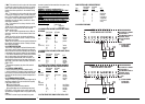
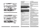
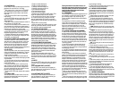
G O Y2 Y1 RC C RH W1 W2 E B
TYPICAL 2 WIRE HEAT HOOKUP
24 VAC AND MILLIVOLT SYSTEMS
XFMR
GAS
VALVE
AC LINE
SYSTEM TYPE = FURNACE
[0
1
]
HEAT STAGES =1
[0
2
]
COMPRESSOR STAGES = 0
[0
3
]
MODES = Heat-Off
[04]
HEAT FAN CONTROL
= GAS
[
09
]
TYPICAL INSTALLER SETUP:
OPTIONAL COMMON
ALLOWS USE OF
SYSTEM POWER
[
1
]
NOTES:
JUMPER
PROVIDED
SYSTEM
COMMON
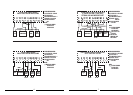
G O Y2 Y1 RC C RH W1 W2 E B
TYPICAL 24VAC 3 WIRE HEAT HOOKUP
WHERE 3RD WIRE IS FAN WIRE
FAN
XFMR
GAS
VALVE
AC LINE
TYPICAL INSTALLER SETUP:
OPTIONAL COMMON
ALLOWS USE OF
SYSTEM POWER
[
1
]
NOTES:
JUMPER
PROVIDED
SYSTEM
COMMON
SYSTEM TYPE = FURNACE
[0
1
]
HEAT STAGES =1
[0
2
]
COMPRESSOR STAGES = 0
[0
3
]
MODES = Heat-Off
[04]
HEAT FAN CONTROL
= GAS
[
09
]