


On replacement installations, mount the new thermostat
in place of the old one unless the conditions listed below
suggest otherwise. On new installations, follow the
guidelines listed below.
●
Do not locate in a damp area. This can lead to corro-
sion that will shorten thermostat life.
●
Do not locate where air circulation is poor, such as in a
corner or an alcove; or behind an open door.
●
Do Locate the thermostat on an inside wall, about 5 ft.
(1.5m) above the floor, and in a room that is used often.
●
Do not install it where there are unusual heating condi-
tions, such as: in direct sunlight; near a lamp, radio, tele-
vision, radiator, register, or fireplace; near hot water pipes
in a wall; near a stove on the other side of a wall.
●
Do not locate in unusual cooling conditions, such as:
on a wall separating an unheated room; or in a draft from
a stairwell, door, or window.
●
Do not install the unit until all construction work and
painting has been completed.
3.3. REMOVAL OF OLD UNIT
CAUTION: Read instructions carefully before removing any
wiring from existing thermostat. Wires must be labeled
before they are removed. When removing wires from their
terminals, ignore the color of the wires since they may not
comply with any standard.
●
Switch electricity to the furnace and air conditioner
OFF; then proceed with the following steps.
●
Remove cover from old thermostat. Most are snap-on
types and simply pull off. Some have locking screws on
the on the side. These must be loosened.
●
Note the letters printed near the terminals. Attach
labels (enclosed) to each wire for identification. Label and
remove wires one at a time. Make sure the wires do not
fall back inside the wall.
●
Loosen all screws on the old thermostat and remove it
from the wall.
3.4. MOUNTING
CAUTION: Be careful not to drop the unit or disturb electronic
parts.
●
Strip insulation 3/8 in. (9.5mm) from wire ends and
clean off any corrosion.
●
Fill wall opening with non-combustible insulation to
prevent drafts from affecting the thermostat.
●
With each thumb on a release tab at the bottom of the
body, and fingers over the top of the unit. Release the
unit from its base plate by squeezing the tabs into the
body.
●
Separate the unit from its base plate by pulling the
body outward from the bottom.
NOTE: If you are mounting the base to a soft material like
plasterboard or if you are using the old mounting holes, the
screws may not hold. Drill a 3/16-in. (4.8mm) hole at each
screw location, and insert the plastic anchors provided. Then
mount the base as described below.
●
Route the wires through the open areas in the base
plate above the terminals. Hold the base against the wall,
with the wires coming through. Position the base for the
best appearance (to hide any marks from an old thermo-
stat). Attach the base to the wall with the two screws pro-
vided.
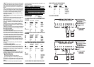
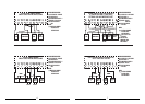
3.5. WIRING
3.5.1 TERMINAL DEFINITIONS
Terminal Definition
1
G
Fan
2
O
Cooling Mode
3
Y2
Second stage cool
4
Y1
First stage cool
5
RC
Cooling power source (transformer +)
6
C
Common, system power -
7
RH
Heating power source (transformer +)
8
W1
First stage heat
9
W2
Second stage heat
10
E
Emergency heat/Freeze protection
11
B
Heating Mode
12
TC
Future Indoor temperature input -
13
T
Future Indoor temperature input +
14
OT
Future Outdoor temperature sensor
input (a)
15
OT
Future Outdoor temperature sensor
input (b)
1.
G
The fan terminal is live at any time the
thermostat attempts to turn the system fan or
blower on.
2.
O
This terminal is live at any time the unit is
in Cool mode.
3.
Y2
Activation of this terminal signifies that the
thermostat is calling for a second stage of cooling.
This terminal will remain inactive unless a second
stage compressor has been specified in the
installer setup menu.
4.
Y1
Activation of this terminal signifies that the
thermostat is calling for a first compressor stage.
This terminal will remain inactive unless at least
one compressor stage has been specified in the
installer setup menu.
5.
RC
This terminal provides power to the cooling
and fan terminals.
6.
C
Use of this terminal allows the unit to be
system powered rather than battery powered. Note
that the display backlight is battery powered only.
7
RH
This terminal provides power to the heating
terminals.
8.
W1
This terminal is active when the thermostat
is calling for the first available stage of furnace or
electric heat. It will remain inactive unless at least
one stage of furnace type heat has been specified
in the installer setup menu.
3
1.FEATURES
●
Universal Compatibility
●
Controls Up To 2 Stages Of Heat And 2 Stages Of
Cooling + Auxiliary and Emergency Heat
●
Large Hybrid Display
●
Auxiliary and Emergency Heat Indicators
●
Electro-luminescent Display Backlight
●
Clean Cycle
®
(Patent No. 6,988,671)
Independently Programmable Fan
●
7 Day Programming
●
Default ENERGY STAR Approved Program
●
4 Periods Per Day
●
Temporary Override
●
Temperature Hold
●
Optional Smart Recovery
●
ENERGY STAR Compliant
●
Programmable Filter Timer With Change
Filter Indicator
●
Energy Usage Monitor
●
F/C Temperature Display
●
12/24 Hour Clock
●
Easy Programming with LUX Speed Dial
®
●
Advanced Copy Function For Fast Easy Programming
●
Nonvolatile Memory For All Programs And Settings
●
Daylight Saving Button
●
Multimode Keyboard Lockout With User
Programmable 3 Digit Code
●
Programmable High And Low Setting Limits
●
Silence-able Audible Button Response
●
Menu Driven Setup Done From The Front Panel
●
Temperature Offset (User Calibration)
●
Dual Power Capable (System/Battery)
●
Multi-Stage Adjustable Temperature Differential /
Cycle Rate
●
Programmable Length Minimum Run Time
●
Programmable Auto-Changeover Dead-Band
●
Programmable Fan Delays For Heat, Cool, In Both
On And Off
2. COMPATIBILITY
Your PSP722E is compatible with most 24 volt gas, oil,
or electrical Heating and/or Cooling systems. It cannot be
used with 120 volt heating systems. Ask your dealer for
other LUXPRO thermostats to control those systems.
2.1. HEAT STAGES
The PSP722E is capable of controlling systems with up
to two stages of heat in furnace mode. In heat pump
mode, the thermostat can be configured to control up to
two stages of compressor driven heat plus auxiliary and
emergency heat stages.
NOTE: AUX HEAT ACTIVATION IS PROVIDED AT
TERMINAL W1
2.2. COOLING/COMPRESSOR STAGES
The PSP722E is capable of controlling systems with up
to two stages of cooling.
2.3. ELECTRICAL RATINGS
●
30V maximum (24VAC nominal)
●
1.5A maximum per terminal
●
2.0A terminal sum
3. INSTALLATION
3.1. TOOLS REQUIRED
●
#1 Phillips screwdriver (small)
●
Drill with 3/16-in. (4.8mm) bit
●
Wire stripper/cutter
3.2. LOCATION
2
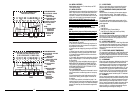
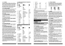
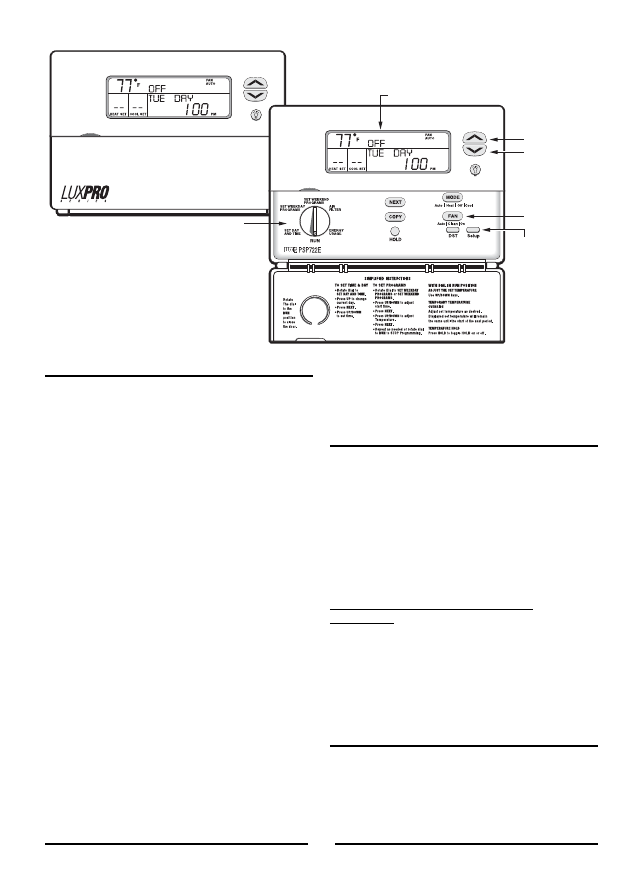
COPY
FAN
MODE
NEXT
NEXT
RUN
DST
Setup
Auto On
SET WEEKEND
PROGRAMS
SET WEEKDAY
PROGRAMS
SET DAY
AND TIME
AIR
FILTER
ENERGY
USAGE
Auto Heat OffCool
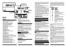
UP
LARGE HYBRID DISPLAY
WITH ELECTRO-LUMINESCENT
DISPLAY BACKLIGHT
EASY
PROGRAMMING
WITH
LUX SPEED DIAL
®
DOWN
IAQ
INDEPENDENTLY
PROGRAMMABLE
FAN
MENU DRIVEN
SETUP
PSP722E