


4.2.4 TEMPERATURE DISPLAY FORMAT (F/C DISPLAY)
Temperature may be displayed in Fahrenheit or Celsius
with this option.
4.2.5 CLOCK FORMAT
The time shown on the thermostats clock may be dis-
played in 12 or 24 hour format. Set this option to your
preference.
4.2.6 CALIBRATION OFFSET
Your thermostat is accurately calibrated at the factory to
within ±1°F An offset value up to ±5°F may be added to
the temperature value that the thermostat measures. This
may allow you to match this thermostat to another.
4.2.7 MAXIMUM HEAT SETTING
The temperature that this option is set to will be the high-
est HEAT SET temperature available in run mode or while
programming the thermostat.
4.2.8 MINIMUM COOL SETTING
The temperature that this option is set to will be the low-
est COOL SET temperature available in run mode or while
programming the thermostat.
4.2.9 SMART RECOVERY
Your thermostats Smart Recovery allows your HVAC sys-
tem to attempt to recover from a setback period and
reach your desired comfort temperature set point by the
beginning of your programmed comfort period. This
option allows you to choose whether to use Smart
Recovery.
If enabled, Smart Recovery will initiate if:
●
Recovery is valid only from a night setback to morning
comfort or day setback to evening comfort period.
●
In Heat mode the temperature set point of the comfort
period must be higher than the setback period.
●
In Cool mode the temperature set point of the comfort
period must be lower than the setback period.
●
The estimated Smart recovery time must be longer
than 15 minutes for an Smart recovery to be initiated.
●
Maximum Smart recovery time is one hour.
●
AUX heat will not be activated during the first half hour
of a Smart recovery. Then it will only be activated if nec-
essary to achieve the programmed temperature by the
beginning of the next period.
●
The Smart recovery temperature set point must be
achievable. If a desired smart recovery is repeatedly
ignored by your thermostat that is an indicator that you
should modify your program so that the recovery can be
achieved within the 1 hour limit.
●
A Smart recovery may not be initiated for 48 hours
after the units programs have been changed. This allows
the unit to gather the data necessary to predict a Smart
recovery time.
4.2.10 FILTER LIMIT
Your thermostat will warn you that your HVAC systems
air filter should be changed after the systems fan has run
the number of hours that this setting has been pro-
grammed for. A general rule of thumb is to assume that
the fan will run at 1/3 duty cycle. A 90 day filter will then
be good for 90*24/3=720 hours. This is the default value.
Setting the filter counter limit to 0000 will disable the
change filter indicator. Valid entries are from 0 to
2000hrs.
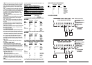
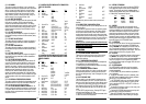
4.2.11 USER SETUP MENU:
Menu
Item
Display Selections Default
01 LOCK KEYPAD NO, PARTIAL, FULL, NEW CODE NO
02 BEEP ON, OFF ON
03 °F/°C DISPLAY °F, °C °F
04 CLOCK FORMAT 12HR / 24HR 12HR
05 CALIBRATION OFFSET ±5°F (±3°C) 0°F
06 MAX HEAT TEMP 45°F-90°F (7°C-32°C) 90°F (32°C)
07 MIN HEAT TEMP 45°F-90°F (7°C-32°C) 45°F (7°C)
08 EARLY RECOVERY ON, OFF OFF
09 FILTER LIMIT 0-2000HRS 720HRS
4.3. ADVANCED FEATURES AND OPERATION
4.3.1 EMERGENCY HEAT
●
To use an emergency heat system, press the MODE
button repeatedly until the EMER HT is shown along the
top of the display. The unit is in emergency heat mode
ready to control your emergency heating system. In heat
pump systems, the emergency heat terminal is often
wired to W1 the AUX heat terminal.
●
Press temperature UP or DOWN keys until your
desired temperature is displayed in the HEAT SET area of
the display.
●
Freeze protection is also provided at this terminal. See
FREEZE PROTECTION.
4.3.2 FAN MODES
Your thermostat provides three fan modes. They are
AUTO, CLEAN, and ON. The fan may be controlled by
your units program, or the program may be overridden
by pressing the FAN button and selecting another mode.
Appropriate indicators are visible along the top of the
units display when active.
4.3.2.1 FAN AUTO
FAN AUTO denotes that the fan will run only to fulfill your
heating and cooling requirements.
4.3.2.2 CLEAN
This enables the CLEAN CYCLE
®
feature. The FAN icon
alone in the display denotes that the fan is maintaining
the programmed minimum run time; it will also run addi-
tional time as required to maintain temperature control.
The algorithm used avoids additional fan time when the
minimum run time has been met over the last hour
through temperature control. Minimum fan run times are
met by running one third the hourly requirement at twen-
ty minute intervals.
4.3.2.3 FAN ON
FAN ON denotes that your system fan will run continu-
ously.
13
required. Heating and cooling set temperatures may not
be adjusted until heating or cooling is necessary, or one
of these modes is manually selected by pressing and
releasing both arrow keys at the same time.
●
You can force heating or cooling to be the active mode
by pressing and releasing both arrow keys at the same
time until the desired mode is indicated. After, the unit
will then switch modes as necessary to control tempera-
ture.
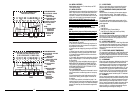
4.1.4.4 HEATING
●
Press the MODE button repeatedly until the word HEAT
is shown along the top of the display. The unit is in HEAT
mode ready to control your heating system.
●
Press temperature UP or DOWN keys until your
desired temperature is displayed in the HEAT SET area of
the display.
●
While heating is active, a flame icon will flash above
the HEAT SET temperature. If a second stage of heat is
called for the flashing rate increases.
4.1.4.5 COOLING
●
Press the MODE button repeatedly until the word
COOL is shown along the top of the display. The unit is in
Cool mode ready to control your air conditioner.
●
Press temperature UP or DOWN keys until your
desired temperature is displayed in the COOL SET area of
the display.
●
While cooling is active, a snowflake icon will flash
above the COOL SET temperature. If a second stage of
heat is called for the flashing rate increases.
4.1.4.6 OFF
●
Press the MODE button repeatedly until the display
indicates that the unit is in OFF.
●
Heating and cooling will be disabled.
●
Periods programmed to maintain a minimum fan run
time will continue do so.
4.1.5 DISPLAY ILLUMINATION
●
Press the light bulb button to illuminate the display.
Pressing other buttons will keep the display illuminated
until no button has been pressed for approximately 20
seconds.
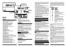
4.2. USER SETUP MENU
User selectable options are available from the User Setup
Menu. To access the User Setup Menu press the Setup
button. All settings, their choices and default values are
given in the USER SETUP MENU:.
4.2.1 ACCESS AND NAVIGATE USER SETUP MENU
●
To scroll through the User Setup Menu one item at a
time, momentarily press Setup Button.
●
Selections can be changed by pressing the UP/DOWN
button.
●
Moving from one menu item to the next and accept-
ance of changes is done by pressing the NEXT button.
●
All changes become effective when the unit exits the
User Setup mode.
●
The User Setup mode will be exited when the Setup
button is pressed again, or if no other keys are pressed
for 20 seconds.
4.2.2 KEYBOARD LOCK
Two types of Keyboard locks allow owners/operators to
prevent unauthorized changes to the thermostats set-
tings. The two types of locks are full and partial. When
the thermostat is locked, a three digit code is set. That
code must be reentered before locked settings can be
changed without performing a software reset off the unit.
Entering a code toggles the selected lock on or off. While
a lock is effective, a padlock is shown near the lower
right corner of the screen.
4.2.2.1 PARTIAL KEYBOARD LOCK
A partial lock allows other users to adjust only the tem-
perature set point to values at or between the Maximum
Heat Setting and Minimum Cool Settings.
4.2.2.2 FULL KEYBOARD LOCK
A full lock disables all the keys except the Setup button
on the front, and the S/W Reset button on the rear.
Pressing the S/W Reset button will rewrite all settings
and programs to their default values.
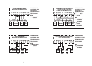
4.2.2.3 SETTING THE LOCK
1. Press SETUP.
2. Select Full or Partial.
3. Press NEXT.
4. Set code one digit at a time. Press NEXT after each
digit.
5. When NEXT is pressed after the third digit has been
entered, the unit will be appropriately locked.
4.2.2.4 CLEARING A LOCK
1. Press SETUP.
2. Enter code one digit at a time. Press NEXT after each
digit.
3. When NEXT is pressed after the third digit has been
entered, the unit will be unlocked if the correct code was
entered.
If you have forgotten the code, your thermostat may be
unlocked by pressing the Software Reset button on the
rear of the unit's circuit board. This will restore the unit to
its default settings and it will likely need to be reconfig-
ured to control your HVAC system.
4.2.2.5 CHANGING THE LOCK CODE
1. Press SETUP.
2. Select NEW CODE.
3. Press NEXT.
4. Enter old code one digit at a time. Press NEXT after
each digit.
5. Enter new code one digit at a time. Press NEXT after
each digit.
6. When NEXT is pressed after the new third digit has
been entered, the new code will be effective.
4.2.3 BEEP
This option allows the audible feedback tone (Beep) to be
enabled or disabled.
12