


3. The pump must run continuously when the burners
are firing.
4. Lubricate the pump to the manufacturers rec om men -
da tions. Pump damage due to inadequate lu bri ca -
tion is non-warrantable.
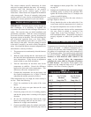
5. A standard water heater/hot water supply boiler is
furnished with a 1/6 HP, 120 VAC, 3.6 AMP
circulating pump to be mounted on the units in let
water connection. This pump is sized based on
installation of a single storage tank and heat er in
close proximity. If the number of fit tings and
straight pipe exceeds the quantities shown in this
sec tion, a larger pump will be required.
The standard pump selection is based on the fol low ing
pipe and fittings from the unit to the stor age tank:
6 - 90° elbows 2 - ball valves
2 - unions 1 - cold water tee
Plus the following length of straight pipe based on the
heater size:
90,000 thru 360,000 Btu/hr Models
Not more than 45 feet of straight pipe
399,999 thru 500,000 Btu/hr Models
Not more than 25 feet of straight pipe
For every elbow and tee in excess of those shown
above, DEDUCT 5 FEET from maximum allowable
straight pipe in heater to tank circulating loop.
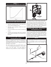
Based on heating potable water with a hardness of 8 to
25 grains per gallon and total dissolved solids not
exceeding 350 ppm. See “Water Chemistry”, page 40.
BTU/hr INPUT
GPM Ft. Hd.
90,000 - 500,000 30 8
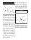
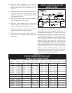
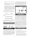
Water heaters are provided with an extra temperature
sensor that MUST BE field installed. The sensor is
shipped loose in the I & O packet. This remote
mounted sensor will be the primary temperature sensor
which will inform the appliance’s built-in thermostat
control. For domestic water heating, the sensor MUST
BE installed into a bulbwell on the storage tank. This
is required to maintain the desired temperature in the
tank and reduce cycling of the heater.
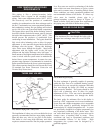
The sensor must also be connected to two blue wires
provided in the upper left-hand corner of the control
panel. It will be necessary to add additional wire to
reach from the appliance to the remote water source.
Use twisted pair wire, minimum 18 gauge or larger. See
Table O, page 38 regarding distance versus wire gauge.
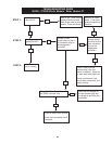
FIG. 50 External Sensor for Tank, System, or Pump Delay
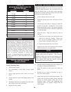
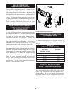
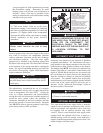
This is a highly sophisticated heat exchanger, de signed
to carry water in such a way that it gen er ates a scour ing
action which keeps all interior sur fac es free from
build-up of impurities. The straight-line, two pass
de sign of the tubes sends water into the headers at a
properly rated velocity. The configuration of the
head ers, in turn, creates a high degree of turbulence
which is sufficient to keep all contaminants in
suspension. This “scouring action” provides greater
cost savings for owners. Tubes are always able to
transfer heat at peak ef fi cien cy. Every surface within
this water con tain ing section is of a nonferrous material,
providing clear, clean, rust-free hot water. Straight
copper tubes-finned on the outside for maximum heat
transfer-glass lined cast iron one piece cored head ers
make up an entirely rustproof unit. On all mod els,
header inspection plugs can be removed for field
in spec tion and cleaning of copper tubes. The entire
heat exchanger may be easily removed from the unit.
1. The thermostat is adjusted to a low test set ting
when shipped from the factory.
2. Set the thermostat to a maximum water
temperature of 125°F which will satisfy hot water
demands and prevent risk of scald injury.
Households with small children or invalids may
require 120°F or lower temperature setting to
re duce risk of scald in ju ry. Some states may
require a lower temperature setting. Check with
41
MINIMUM PUMP PERFORMANCE
EXTERNAL SENSOR FOR TANK, SYSTEM OR PUMP DELAY
REMOTE SENSOR CONNECTOR IS
LOCATED ON SIDE OF UNIT.
NOTE: COLOR OF WIRES AND
LEAD STYLES MAY VARY
WITH SENSOR PROVIDED.
CONNECTIONS ARE POLARITY
INSENSITIVE.
SIDE PANEL
HEAT EXCHANGER
THERMOSTAT SETTINGS
REMOTE SENSOR
INSTALLATION INSTRUCTIONS