


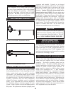
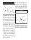

The operating temperature control is located in the
control panel, behind the control panel front ac cess door.
The sensing element for the operator is placed in a bulb
well installed in the heat exchanger. Carefully observe
the dis charge water temperature on the initial boiler on
cycles. The exact temperature set point is based on your
system’s requirements. Turn the con trol set point dial to
the desired operating water tem per a ture. Observe the
boiler discharge tem per a ture after each set point
adjustment to ensure prop er operation.
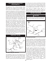
A room thermostat or remote temperature control may
be connected to the boiler. The room ther mo stat should
be installed on an inside wall, away from the influences
of drafts, hot or cold water pipes, lighting fixtures,
televisions, sun rays or fire plac es. Follow the
manufacturers instructions supplied with the ther mo stat
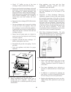
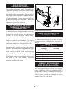
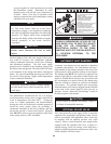
for proper installation and ad just ment. The boiler is
equipped with a terminal strip on the left side of the
control panel to allow easy connection (Figure 48).
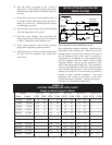
Remove the jumper between the R and W terminals on
the terminal strip. Refer to the chart in this section to
determine maximum allowable length and wire gauge
recommended to connect the switching con tacts of the
room thermostat to the R and W terminals on the
terminal strip. Connection to the terminal strip will
allow the room thermostat to make and break the
24VAC boiler control circuit turning the boiler on and
off based on the room ambient temperature
re quire ments. Set the boiler operating temperature
control as described in this section
FIG. 48 Terminal Strip Connections
A terminal connection strip is provided for ease of
connection for Power Venting Systems, see Figure 48,
inset A.
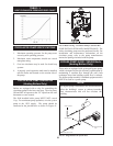
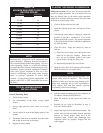
This section applies only to those units used to sup ply
direct fired domestic hot water and installed with a
storage tank(s). The use of a properly sized pump and
the control of water velocity, as ex plained in the Water
Velocity Control section, are important for correct
operation of your hot water heater.
38
A
Wire Gauge Maximum
Allowable Length
12 GA 100 ft
14 GA 75 ft
16 GA 50 ft
18 GA 30 ft
TABLE - O
TERMINAL STRIP WIRING
BOILER OPERATING
TEMPERATURE CONTROL
ROOM THERMOSTAT OR REMOTE
THERMOSTAT CONNECTION
TO TERMINAL STRIP
DOMESTIC WATER HEATERS
90,000 - 500,000 Btu/hr MODELS
POWER VENTER CONNECTION
TO TERMINAL STRIP